
Free Software Download Center
Software for industrial data collection, monitoring, and analysis.
EOS SCADA • ANALOG METER • USER CONTROL
ANALOG METER (ANALOG_METER) is a simple and practical user control designed to display continuously changing process values on EOS SCADA screens in a traditional analog gauge format.
The gauge can be configured by the user with settings such as minimum and maximum value ranges, pointer angle, pointer color, and the frequency, thickness, and size of minor, intermediate, and major scale divisions.

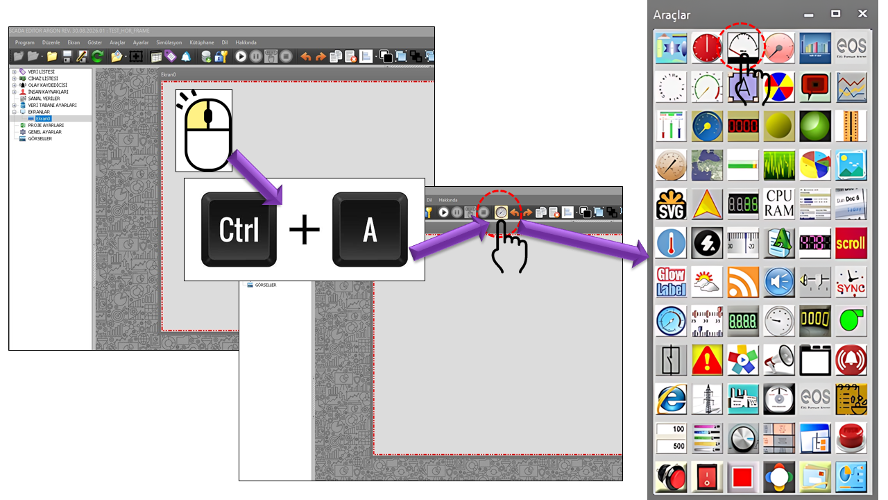
ANALOG METER is a user control in EOS SCADA implemented as the ANALOG_METER User Control type. It is designed to visually display an analog process value using a dial and a moving pointer.
Its basic operating principle is straightforward: a process value is positioned on the analog dial according to the measurement range defined by MinValue and MaxValue, and is indicated by the pointer whose color is defined by PointerColor. The starting angle of the dial scale is determined by TickStartAngle.
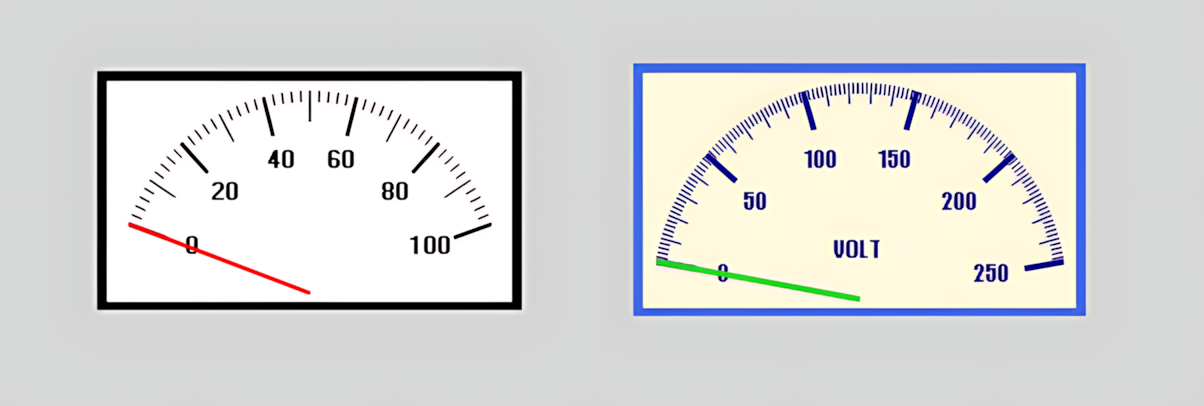
Dial readability can be adjusted through independently configurable frequency, line thickness, and size settings for minor, very minor, and major scale marks. The same control can therefore be used to display pressure, temperature, flow rate, level, motor speed, power, current, voltage, and other continuous analog values that operators need to recognize quickly on SCADA screens.
Basic principle: ANALOG_METER is neither a trend chart nor a numerical display. It presents an instantaneous analog value to the operator as a quick visual reference using a conventional dial and moving pointer.
When configuring ANALOG METER, first define the measurement range and the dial's starting angle, then adjust the appearance of the pointer and scale marks.
MinValue and MaxValue.TickStartAngle.SCADA systems can display analog process variables received from sensors and instruments on operator screens. Common analog variables include level, temperature, pressure, flow rate, and motor speed. citeturn0search1turn0search7
Pressure, temperature, flow rate, and level are among the fundamental measurement variables used in industrial process instrumentation. These variables can be continuously monitored in power plants, process industries, refineries and petrochemical facilities, water treatment plants, and similar installations. citeturn0search0turn0search9
| Variable | Example Application | Display Approach |
|---|---|---|
| Pressure | Pipeline, tank, boiler, or process pressure | The Min/Max range is set according to the pressure measurement range. |
| Temperature | Process, equipment, or fluid temperature | The pointer indicates the instantaneous value within the temperature range. |
| Flow Rate | Water, steam, gas, or process flow | A wide measurement range and readable scale marks can be used. |
| Level | Tank, reservoir, or process level | The measurement range can be configured as a percentage or a physical level unit. |
| Speed | Motor, pump, fan, or turbine speed | Helps operators quickly recognize the instantaneous speed from the dial. |
| Electrical Quantities | Continuous values such as current, voltage, and power | The value range is configured according to the engineering unit of the relevant electrical quantity. |
Note: This control is intended for display purposes only. Using an analog meter on a SCADA screen does not, by itself, guarantee measurement accuracy or ensure that the process value is being measured correctly in the physical system. The measurement range, scaling, sensor/transmitter, input card, and SCADA data-processing chain must also be configured correctly.
General properties define the control's basic operating and
appearance settings. UpdateInterval specifies how
frequently the displayed value is refreshed.
| Property | EOS Turkish Equivalent | Default | Purpose | Where It Is Used |
|---|---|---|---|---|
UCType |
Control Type | ANALOG_METER |
Defines the User Control type within EOS SCADA. | In the basic configuration where the control is defined as ANALOG_METER. |
UCName |
Control Name | Empty |
Specifies the name of the user control. | On screens where the control needs to be identified in the editor. |
UpdateInterval |
Update Interval | 1000 ms |
Specifies the control's update interval. | On screens where analog process values are refreshed periodically. |
UCBackColor |
Control Background Color | White |
Specifies the control's background color. | For the dial's background appearance. |
UCForeColor |
Control Foreground Color | Black |
Specifies the control's primary foreground color. | For the appearance of the title and text displayed on the dial. |
UCFont |
Control Font | Arial Narrow, 8.25 pt, Bold |
Specifies the control's primary font settings. | For the appearance of titles and meter text. |
These properties define the analog meter's measurement range and the geometric starting point of the dial. MinValue and MaxValue define the engineering value range, while TickStartAngle specifies the starting angle of the first scale mark.
| Property | EOS Turkish Equivalent | Default | Purpose | Where It Is Used |
|---|---|---|---|---|
BorderColor |
Border Color | Black |
Specifies the color of the meter's outer border. | For the appearance of the analog meter's outer boundary on the screen. |
TitleText |
Title Text | Empty |
Specifies the meter's title text. | For displaying variable names such as Pressure, Temperature, Flow Rate, or Power. |
MinValue |
Minimum Value | 0 |
Defines the lower measurement limit of the analog meter. | For the minimum engineering value of the process variable being displayed. |
MaxValue |
Maximum Value | 100 |
Defines the upper measurement limit of the analog meter. | For the maximum engineering value of the process variable being displayed. |
TickStartAngle |
Scale Starting Angle | 20 |
Specifies the starting angle of the dial's scale marks. | To adjust the angle at which the dial's measurement range visually begins. |
PointerColor specifies the color of the moving pointer that indicates the analog value on the dial. The pointer directly communicates the corresponding measurement value to the operator visually.
| Property | EOS Turkish Equivalent | Default | Purpose | Where It Is Used |
|---|---|---|---|---|
PointerColor |
Pointer Color | Red |
Specifies the color of the pointer that indicates the analog value. | To distinguish the pointer from other visual elements on the dial. |
Minor scale marks divide the main scale into regular intervals. TickSmallFrequency specifies their frequency, TickSmallWidth specifies their line thickness, and TickSmallSize specifies their size.
| Property | EOS Turkish Equivalent | Default | Purpose | Where It Is Used |
|---|---|---|---|---|
TickSmallFrequency |
Minor Scale Mark Frequency | 10 |
Specifies the intervals at which minor scale marks are created. | For creating the dial's basic measurement divisions. |
TickSmallWidth |
Minor Scale Mark Width | 1 |
Specifies the thickness of minor scale mark lines. | For the appearance of minor scale lines. |
TickSmallSize |
Minor Scale Mark Size | 15 |
Specifies the length of minor scale mark lines. | To adjust the visibility of minor scale lines on the dial. |
Very minor scale marks create finer intermediate divisions between minor scale marks. They are particularly useful when a more precise-looking dial is required.
| Property | EOS Turkish Equivalent | Default | Purpose | Where It Is Used |
|---|---|---|---|---|
TickTinyFrequency |
Very Minor Scale Mark Frequency | 2 |
Specifies the intervals at which very minor scale marks are created. | For intermediate scale lines between minor scale marks. |
TickTinyWidth |
Very Minor Scale Mark Width | 1 |
Specifies the thickness of very minor scale mark lines. | For the appearance of fine intermediate scale lines. |
TickTinySize |
Very Minor Scale Mark Size | 5 |
Specifies the length of very minor scale mark lines. | For creating fine intermediate divisions on the dial. |
Major scale marks form the dial's primary scale indicators. They are particularly important for helping operators read the dial quickly.
| Property | EOS Turkish Equivalent | Default | Purpose | Where It Is Used |
|---|---|---|---|---|
TickLargeFrequency |
Major Scale Mark Frequency | 20 |
Specifies the intervals at which major scale marks are created. | For marking the primary scale values on the dial. |
TickLargeWidth |
Major Scale Mark Width | 2 |
Specifies the thickness of major scale mark lines. | To distinguish primary scale lines from minor scale marks. |
TickLargeSize |
Major Scale Mark Size | 20 |
Specifies the length of major scale mark lines. | For the appearance of primary scale lines on the dial. |
Using TitleText="PRESSURE", process pressure within
a range such as 0–10 bar can be monitored using a conventional
analog dial. Major scale marks can indicate the primary pressure
divisions, while minor scale marks show intermediate values.
A suitable dial can be created for process or equipment
temperature using TitleText="TEMPERATURE".
MinValue and MaxValue are set
according to the temperature engineering range.
Using TitleText="FLOW RATE", the instantaneous
flow rate of water, steam, or gas can be displayed with an
analog pointer. Major, minor, and very minor scale marks can
be adjusted according to the flow measurement range.
The same control can be adapted to other continuously varying
analog process values, such as electrical power, motor speed,
or tank/reservoir level. The variable's engineering range is
defined using MinValue and MaxValue.
When designing an analog meter, it is important not only to position the pointer correctly but also to ensure that operators can read the dial quickly. Making major scale marks prominent, minor marks finer, and very minor marks lighter when appropriate can strengthen the dial's visual hierarchy.
Recommendation: Using too many scale marks
can reduce readability. The values of
TickLargeFrequency,
TickSmallFrequency, and
TickTinyFrequency should be selected by
considering the measurement range, the resolution required
by the operator, and the physical size of the screen.
| Group | Properties | Primary Purpose |
|---|---|---|
| General | UCType, UCName, UpdateInterval, UCBackColor, UCForeColor, UCFont |
Basic operating and appearance settings of the control |
| Dial | BorderColor, TitleText, MinValue, MaxValue, TickStartAngle |
Scale, title, and dial geometry |
| Pointer | PointerColor |
Display of the instantaneous analog value |
| Minor Scale Marks | TickSmallFrequency, TickSmallWidth, TickSmallSize |
Basic intermediate scale |
| Very Minor Scale Marks | TickTinyFrequency, TickTinyWidth, TickTinySize |
Fine intermediate scale |
| Major Scale Marks | TickLargeFrequency, TickLargeWidth, TickLargeSize |
Primary scale indicators |
ANALOG_METER (ANALOG METER) is a straightforward user control that enables continuously changing analog process values to be monitored quickly on EOS SCADA screens using a conventional dial and pointer.
Because the minimum and maximum value range, starting angle, pointer color, and three different levels of scale marks can be configured independently, the same control can be adapted to different process variables and screen designs.
It can be used as a complementary indicator alongside trend charts and numerical value displays, particularly on screens where operators need to perceive an instantaneous value visually before reading it as a number.
Source note: The application areas described on this page are supported by general industrial application sources covering the monitoring of analog variables in SCADA systems and the use of industrial instrumentation for variables such as pressure, temperature, flow rate, and level.
Free Software Download Center
Software for industrial data collection, monitoring, and analysis.

Technical Support
Software documentation, sample code, and practical technical information.
You can contact us regarding EOS software, technical documentation, or industrial data communication.