
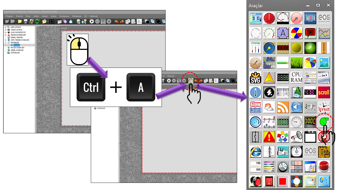
About INDUSTRIAL LED (INDUSTRIAL SHAPE INDICATOR)

The core idea behind INDUSTRIAL_LED is to represent process information not only through numerical values, but also through industrial symbols that operators can recognize at a glance. When a shape is connected to a data source, the operating status, warning level, or alarm level of a process can be represented visually.


Therefore, this control offers more than simply displaying individual symbols: it provides a structure that can establish the visual language of a SCADA screen. Screen design can begin with the ready-made vector shapes in the library, while external image files can be used for specialized requirements.

One Control, Multiple Ways to Visualize Information

The same control can be used as an equipment symbol, status indicator, operating/fault indicator, alarm graphic, or symbolic screen element representing process status. Especially in systems containing large numbers of devices, the symbol itself becomes a status layer that conveys direct meaning to the operator.

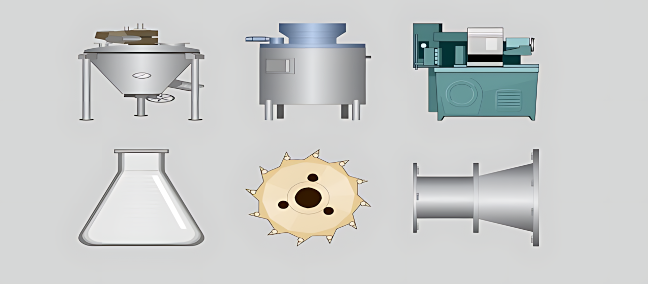
Vector Industrial Shape Library

One of the control's strongest features is the ability to select from a collection of ready-made industrial shapes. Instead of drawing each equipment symbol from scratch, a suitable symbol can be selected and placed directly on the SCADA screen. Based on the user's requirements, a shape that is not available in the library can also be defined using an external image file.

Data-Driven Shapes and Alarm States

A second feature that makes INDUSTRIAL_LED powerful is that the shape is not merely a static image. Depending on whether the connected data reaches specified thresholds, the control can apply different shape data states. This allows the same equipment symbol to visually represent different operating conditions, such as normal, warning, and alarm states.

1. DataSCADA process value
2. ThresholdLevelThreshold
3. StateSHAPEDataStates
4. VisualColor or shape
5. AlarmBlinking, if required

Colored — Color Change

The vector shape itself remains unchanged; its visual color changes according to the data state. This approach is suitable when the equipment symbol must retain a consistent shape while its operating status is distinguished through color.

Normal
Warning
Alarm
Information

Shapechange — Shape Change

The shape itself is changed. The replacement shape can be selected from the library, or an external image file can be used. This makes it possible to represent alarm levels not only through color changes, but also through changes to the symbol itself.

Normal → Standard Symbol Warning → Alternative Symbol Alarm → Alarm Symbol

Visual Alarm Design

Color changes and shape changes are visual layers that help operators distinguish states quickly. When designing alarm levels, readability can be improved by ensuring that a condition can be distinguished not only by color, but also, where necessary, by a change in shape or blinking behavior. The thresholds and state logic described here are defined through the SHAPEDataStates collection.

Shape Data States Collection

SHAPEDataStates is at the center of INDUSTRIAL_LED's state-based visual behavior. For each state, the threshold, visibility, blinking behavior, and shape/image information to be used can be defined.

Property English Equivalent Description
LevelBackColor Level Background Color Sets the background color for the data state.
LevelForeColor Level Foreground Color Sets the foreground/text color for the data state.
LevelThreshold Level Threshold The threshold value used to determine the state.
BlinkActive Blinking Enabled Enables blinking behavior for the corresponding state.
ImageFileName Image File Name The external image file to be used for the state.
LibrarySelectedImage Selected Library Image The image selected from the library for the state.
LibraryImage Library Image The library image object.
Visible Visible Determines whether the corresponding shape state is displayed.

Shape Orientation, Rotation, and Color Processing

The orientation and visual processing of an industrial symbol are just as important as its position on the screen. INDUSTRIAL_LED provides rotation and axis-flipping options so that ready-made shapes can be used in different orientations. Precise rotation also provides angle control beyond the basic orientation options when required.

Property English Equivalent Default Role
RotationAngle Rotation Angle 0 Degrees Defines the basic rotation of the shape.
XFlip Flip X false Flips the shape along the X-axis.
YFlip Flip Y false Flips the shape along the Y-axis.
UsePreciseRotation Use Precise Rotation false Enables precise angle control.
PreciseAngle Precise Angle 0 The angle value used for precise rotation.
ColorAutoSelect Automatic Color Selection false An option that automates color selection behavior.
RedComponent Red Component 175 The red component value used in color processing.
GreenComponent Green Component 175 The green component value used in color processing.
BlueComponent Blue Component 175 The blue component value used in color processing.
PixelTreshold Pixel Threshold 100 The threshold value used for image/pixel processing.

GNAciBilgisi — Orientation Options

0 Degrees, 90 Degrees, 180 Degrees, and 270 Degrees provide the standard orientation options. When precise rotation is enabled, the PreciseAngle value can also be used.

General Properties

Property English Equivalent Default Description
UCType Control Type INDUSTRIAL_LED Specifies the operating type of the control.
UpdateInterval Update Interval 1000 ms The interval at which the control updates its data/visuals.
DecimalPoint Decimal Places 0 Sets the number of decimal places for numeric display.
UCFont Control Font Arial Narrow, 8.25 Bold The font used for control text.
AlarmType Alarm Type Colored Determines whether data states are represented through color changes or shape changes.
BlinkRate Blink Rate 1000 ms The timing value used when blinking is enabled.
UCBackColor Control Background Color Transparent The background color of the control.
UCForeColor Control Foreground Color Black The foreground/text color of the control.
DefaultImageFileName Default Image File Name "" The default external image file.
DefaultLibraryImage Default Library Image "" The default image selected from the library.
DefaultImage Default Image null The default image object.
FilterText Filter Text "" The text used to filter items in the shape library.
UseFillColor Use Fill Color false Enables the use of a fill color for the shape.
FillColor Fill Color Lime The color applied when fill coloring is used.
SHAPEDataStates Shape Data States — The collection in which visual behavior is defined according to thresholds and states.

Alarm Types — Options

ILAlarmTuru determines how a data state is represented on the symbol. There are two basic visual approaches:

Option English Equivalent Behavior
Colored Color Change The vector shape itself remains unchanged; its color changes according to the data state.
Shapechange Shape Change The shape itself changes according to the data state; the replacement shape can be selected from the library or an external image.

Applications

Electrical Power

Symbolic status display for circuit breakers, disconnectors, motors, transformers, and other field equipment.

Hydroelectric Facilities

Visual status monitoring of turbine auxiliary systems, pumps, valves, and flow equipment.

Manufacturing Facilities

Symbolic representation of operating, warning, and alarm states for motors, conveyors, fans, pumps, and process machinery.

Water and Wastewater

Symbolic representation of pumping stations, tanks, valves, and flow lines on operator screens.

Temperature and Pressure Processes

Highlighting the status of the relevant equipment visually, instead of or alongside displaying the measurement value itself.

General SCADA Screen Design

Creating consistent, readable, equipment-focused screens using ready-made shapes and custom images.

Establishing the Visual Language of a SCADA Screen

The real strength of INDUSTRIAL_LED lies in its ability to start with a single equipment symbol and represent many devices using the same visual logic. Using a consistent symbolic approach for motors, pumps, valves, and tanks throughout a facility creates design consistency that helps operators recognize equipment and distinguish its status on screen.

Example of Visual Logic

Normal: standard equipment symbol → Warning: the same symbol in a different color or an alternative shape → Alarm: alarm symbol and blinking, if required → Recovery: return to the normal symbol.

This approach can be used to position visual status information alongside numerical values, particularly on main process screens where many items of equipment are monitored simultaneously.

Library + Data + State = Visual SCADA

INDUSTRIAL_LED can be understood in terms of three fundamental layers: shape selection, data connection, and state-dependent visual behavior. Combining these layers transforms the user control from an ordinary image component into a visual representation layer for the process.

Recommended Design Approach

  1. Identify the equipment: Determine the symbolic representation of the process equipment to be displayed.
  2. Select a shape from the library: Find a suitable industrial vector shape and use it as the default image.
  3. Use a custom image if necessary: Specify an external image file for a symbol that is not available in the library.
  4. Connect the data: Associate the shape with the relevant process data.
  5. Define state thresholds: Configure LevelThreshold and the corresponding visual behaviors in SHAPEDataStates.
  6. Select the alarm type: Use Colored when a color change is sufficient, or Shapechange when the symbol itself must also change.
  7. Keep the screen uncluttered: Design visual changes to be meaningful, consistent, and easy for operators to distinguish quickly.

Conclusion

INDUSTRIAL_LED is one of the industrial visualization components in EOS SCADA. When its library of thousands of vector industrial shapes, support for external images, data connectivity, threshold-based SHAPEDataStates structure, and color- and shape-changing options are considered together, it becomes clear that the control is more than a simple LED indicator. It can be used to create a powerful symbolic system for representing the status of equipment throughout an entire screen.

This approach, which links the symbol itself to process data, is a valuable design tool, particularly on large SCADA screens where operators need to answer the questions "Which equipment is where, and what is its current state?" at a glance.
