Circuit Breaker
A circuit breaker is a switching device that can open and close a circuit under normal operating conditions and interrupt current under fault conditions. High-voltage AC circuit breakers are covered by IEC 62271-100.
EOS SCADA • CIRCUIT BREAKER • CIRCUIT BREAKER / DISCONNECTOR • STATUS AND COMMAND USER CONTROL
CIRCUIT BREAKER is a critical user control used to monitor the status of circuit breakers and disconnectors on SCADA screens in power plants and high-voltage electrical installations, and to send OPEN / CLOSE commands to authorized operators.
The control evaluates open and closed position feedback through separate SCADA tag data, updates its visual state, and can combine authorization and verification mechanisms for command execution. Therefore, CIRCUIT BREAKER is more than just a symbol; it is an operational control that brings together monitoring, command execution, authorization, and status verification in one place.

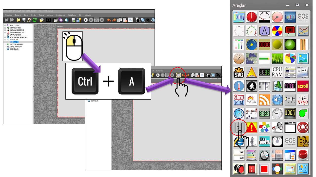
Electrical power plants use various switching devices to manage electrical energy safely between generating units, transformers, lines, busbars, and auxiliary systems. The CIRCUIT BREAKER control links the symbolic representation of these devices on the SCADA screen to actual field feedback.
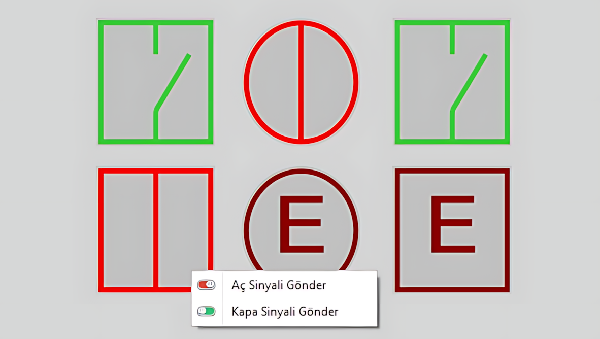
A circuit breaker is a switching device that can open and close a circuit under normal operating conditions and interrupt current under fault conditions. High-voltage AC circuit breakers are covered by IEC 62271-100.
A disconnector is a switching device used to establish a safe isolation gap in an electrical circuit and clearly indicate that equipment has been disconnected from the circuit. IEC 62271-102 covers AC disconnectors and earthing switches and includes requirements relating to position indication.
Although both may be displayed using open/closed positions on a SCADA screen, their electrical functions are not the same. The primary function of a circuit breaker is to switch a circuit and interrupt current when necessary, whereas a disconnector is primarily intended for isolation. Therefore, control sequences, interlocks, and field operating procedures must be designed according to the actual function of the equipment.
The status evaluation performed by the CIRCUIT BREAKER control does not depend on a single data format. The evaluation method changes according to how the feedback Tags are configured. DataMeasuredOpen and DataMeasuredClosed are SCADA Tag values used to read the current field position. On the command side, DataCommandOpen and DataCommandClosed are used to transfer OPEN/CLOSE commands issued by authorized users to the corresponding SCADA Tag values.
If both DataMeasuredOpen and DataMeasuredClosed are available, the control evaluates the two feedback signals together. This method identifies not only whether the equipment is open or closed, but also whether the two position signals are consistent with each other.
| Open Feedback | Closed Feedback | Displayed Status | Algorithm Interpretation |
|---|---|---|---|
>= 1 |
< 1 |
OPEN | The open-position signal is active, while the closed-position signal is inactive. |
< 1 |
>= 1 |
CLOSED | The closed-position signal is active, while the open-position signal is inactive. |
>= 1 |
>= 1 |
ERROR | Both open and closed feedback signals are active simultaneously; a status inconsistency is indicated. |
0 |
0 |
UNDETERMINED | Both position feedback signals are inactive; the control cannot confirm a specific position. |
In the algorithm branch where both feedback signals are evaluated together, the explicitly handled cases are >= 1 / < 1, < 1 / >= 1, >= 1 / >= 1, and 0 / 0. For example, if both values are less than 0, no separate status is assigned in this branch. Therefore, the status table describes the actual behavior of the supplied evaluation algorithm, not a general electrical standard.
If DataMeasuredOpen is configured but DataMeasuredClosed is not, the control switches to a different data-encoding approach. In this scenario, the value of the single Tag is interpreted directly as a status code.
DataMeasuredOpen Value |
Displayed Status | Algorithm Interpretation |
|---|---|---|
0 |
UNDETERMINED | Open feedback is inactive. |
1 |
OPEN | Open status code. |
2 |
CLOSED | Closed status code. |
3 |
ERROR | Error status code. |
This arrangement allows UNDETERMINED, OPEN, CLOSED, and ERROR statuses to be represented using a single data value, without requiring a second closed-feedback Tag. Therefore, the project design must specify whether feedback is provided through two separate Tags or as a single status code.
If DataMeasuredClosed is configured but DataMeasuredOpen is not, the algorithm follows a third evaluation path. In the supplied implementation, the OPEN display is selected when DataMeasuredClosed >= 0, while the CLOSED display is selected when DataMeasuredClosed < 1.
DataMeasuredClosed |
Displayed Status | Condition in the Source Algorithm |
|---|---|---|
>= 0 |
OPEN | BARAKAPALIDATA >= 0 |
< 1 |
CLOSED | BARAKAPALIDATA < 1 |
These conditions overlap mathematically: the value 0 satisfies both >= 0 and < 1. However, because of the order of the code's if ... else if statements, the >= 0 condition is evaluated first, and the value 0 is displayed as OPEN. Therefore, this behavior should not be interpreted using the general assumption that “closed feedback is 0.” The existing Tag encoding and the order of the algorithm's conditions must be considered together.
If none of the configured data paths satisfies a valid condition, the control displays UNDETERMINED. This means that the control cannot reliably confirm a specific field position. When configuring SCADA Tags, it is particularly important to distinguish between “no data,” “invalid data,” and values representing the actual field status.
Depending on the project configuration, the same visual user control can operate with different feedback models: two separate position feedbacks, multiple status codes in a single Tag, or a single position feedback. Therefore, the meaning of Tag values should not be assumed based solely on the control's appearance. The project documentation should explicitly state which evaluation branch the data model uses and how its values are encoded.
Reading the status and sending a control command are separate operations. DataMeasuredOpen and DataMeasuredClosed are used to read the field status, while DataCommandOpen and DataCommandClosed are used to write command values. This distinction makes it clear that an operator's command and the actual status reported from the field are not the same thing.
Command authorization is a critical operational parameter. Using the user control for monitoring and using it to send OPEN/CLOSE commands to a circuit breaker or disconnector must not be treated as requiring the same authorization level. The level specified by AuthorizationLevel is particularly important for access to the command menu. When RequestVerification is enabled, an additional verification mechanism can also be used.
The control can display open, closed, undetermined, and error states in different colors to help operators quickly identify the electrical status on the SCADA screen.
StateOpenColor
Default: Color.LimeGreen
StateClosedColor
Default: Color.Red
StateUndeterminedColor
Default: Color.DimGray
StateErrorColor
Default: Color.DarkRed
These colors are not merely decorative. They provide visual status coding that helps operators quickly distinguish the current equipment position and feedback consistency, particularly in power facilities.
The most critical feature of the CIRCUIT BREAKER control is its ability to send commands, going beyond simply displaying status. Users can select the appropriate OPEN or CLOSE command from the status menu opened with a right-click on the control. The command target is the SCADA Tag specified by DataCommandOpen or DataCommandClosed.
RequestVerification is enabled, verification is requested before the operation.DataMeasuredOpen / DataMeasuredClosed, and the symbol's displayed status is updated to reflect the actual state.Sending an OPEN or CLOSE command does not mean that the circuit breaker has physically reached that position. The measured status feedback is the reliable operational indication for the CIRCUIT BREAKER control. This is why command data and field feedback must be kept separate.
AuthorizationLevel is a critical security parameter that determines the user authorization level required to use the control's command function. Its default value is Monitor. In actual operating scenarios, OPEN/CLOSE commands should be available only to appropriately authorized users.
| Enumeration | English | Meaning in the CIRCUIT BREAKER Control |
|---|---|---|
None |
No Authorization | No command authorization is granted. |
Monitor |
Monitoring | Used for status monitoring; command authorization should not be granted. |
Operation |
Operation | An authorization level that can be used for operational control. |
Engineering |
Engineering | Represents access for users with engineering-level privileges. |
Superuser |
Superuser | The highest defined user level. |
When RequestVerification is enabled, additional verification can be requested before an OPEN/CLOSE operation. VerificationLevel specifies the verification level, while StateOpenVerificationMessage and StateClosedVerificationMessage specify the verification messages displayed for OPEN/CLOSE operations.
The authorization level should not be treated merely as an interface option. Circuit breaker and disconnector controls must be considered together with field interlocks, electrical interlocks, operating procedures, and authorized personnel roles.
Four values on the command side distinguish the reading of field status from the generation of commands. Open/closed status feedback is obtained from measured data, while OPEN/CLOSE operations are performed through command data.
| Property | EOS Turkish Equivalent | Role |
|---|---|---|
DataMeasuredOpen |
Measured Data Open | Circuit Breaker/Disconnector Open Measured Data; reads feedback for the current open position. |
DataMeasuredClosed |
Measured Data Closed | Circuit Breaker/Disconnector Closed Measured Data; reads feedback for the current closed position. |
DataCommandOpen |
Open Command | Specifies the Tag data to which the OPEN command for the circuit breaker/disconnector is written. |
DataCommandClosed |
Close Command | Specifies the Tag data to which the CLOSE command for the circuit breaker/disconnector is written. |
Measured Data describes the current field status, whereas a Command sends an operation request to the field equipment. Treating these two data paths as separate concepts is a fundamental principle for correctly interpreting SCADA control screens.
| Property | EOS Turkish Equivalent | Default | Description |
|---|---|---|---|
StateOpenOnValue |
Open On Value | 1 |
The value used for the open state in command data. |
StateOpenOffValue |
Open Off Value | 0 |
The inactive/off value of the open command data. |
StateClosedOnValue |
Closed On Value | 1 |
The value used for the closed state in command data. |
StateClosedOffValue |
Closed Off Value | 0 |
The inactive/off value of the close command data. |
PulseDelayTime |
Pulse Delay Time | 500 ms |
A timing parameter associated with the command pulse duration. |
SwitchType |
Switch Type | Circuitbreaker |
Specifies whether the control is used as a circuit breaker or a disconnector. |
| Enumeration | English | Usage |
|---|---|---|
Circuitbreaker |
Circuit Breaker | For the circuit breaker symbol and behavior. |
Disconnector |
Disconnector | For the disconnector symbol and behavior. |
Properties such as ShapeWidth Shape Width, ShapeAngle Shape Angle, MirrorImage Mirror Image, and DisplayBorder Display Border control the symbol's visual presentation on the SCADA screen.
FastResponseMode provides a separate algorithmic path for responding more quickly to the status of critical circuit breakers and disconnectors that may need to open very rapidly. This feature should be considered particularly for equipment where handling an opening event faster than the normal update cycle is operationally important.
Fast Response Mode should not be enabled for every CIRCUIT BREAKER control. Using this special fast-response path for too many controls can increase the processing load on the SCADA system and negatively affect overall performance. Therefore, it is appropriate to reserve this mode for critical circuit breakers/disconnectors where rapid status changes are operationally significant.
Critical generator output circuit breaker: Fast Response Mode may be considered when rapid status response is operationally important.
Large numbers of secondary disconnectors: If no special fast-response requirement exists, the standard update mechanism should be preferred to avoid unnecessary processing load.
Because the CIRCUIT BREAKER control can be used on many screens and for many pieces of equipment, the total screen workload must be considered, not just the behavior of an individual control.
UpdateInterval = 1000 specifies the control's normal update interval. The total update workload should be considered when many controls are used.
FastResponseMode can be used for a limited number of critical circuit breakers/disconnectors that require a faster response.
When many circuit breaker symbols are displayed on a single screen, colors, orientations, and positioning should remain consistent, and error and undetermined states should be easy to distinguish.
| Property | EOS Turkish Equivalent | Default | Description |
|---|---|---|---|
UCType |
Control Type | KESICI |
Specifies the type of the user control. |
UpdateInterval |
Update Interval | 1000 ms |
Specifies the normal status update cycle. |
DecimalPoint |
Decimal Places | 0 |
Specifies the number of decimal places used for numeric data display. |
UCBackColor |
Control Background Color | Transparent |
Specifies the background color of the control. |
UCForeColor |
Control Text Color | Black |
Specifies the text color of the control. |
UCFont |
Control Font | Arial Narrow 8.25 |
Specifies the font used by the control. |
AuthorizationLevel |
Authorization Level | Monitor |
Specifies the authorization level required to use the control's command functions. |
FastResponseMode |
Fast Response Mode | false |
Enables a special algorithm for rapid status response on critical equipment. |
| Property | EOS Turkish Equivalent | Default | Function |
|---|---|---|---|
StateOpenColor |
Open State Color | LimeGreen |
Specifies the visual color of the open state. |
StateClosedColor |
Closed State Color | Red |
Specifies the visual color of the closed state. |
StateUndeterminedColor |
Undetermined State Color | DimGray |
Used when the status cannot be determined. |
StateErrorColor |
Error State Color | DarkRed |
Highlights contradictory or erroneous status indications. |
RequestVerification |
Request Verification | false |
Enables a verification step before a command is issued. |
VerificationLevel |
Verification Level | 1 |
Specifies the verification level. |
StateOpenVerificationMessage |
Open State Verification Message | "" |
The verification message for the OPEN command. |
StateClosedVerificationMessage |
Closed State Verification Message | "" |
The verification message for the CLOSE command. |
MirrorImage |
Mirror Image | false |
Displays a mirrored version of the symbol. |
DisplayBorder |
Display Border | false |
Displays the control border. |
| Enumeration | English | Description |
|---|---|---|
GNKesiciTuru.Circuitbreaker |
Circuit Breaker | Circuit breaker representation. |
GNKesiciTuru.Disconnector |
Disconnector | Disconnector representation. |
GNYetkiSeviyesi.None |
No Authorization | No command authorization. |
GNYetkiSeviyesi.Monitor |
Monitoring | Monitoring-level access. |
GNYetkiSeviyesi.Operation |
Operation | Operational-level access. |
GNYetkiSeviyesi.Engineering |
Engineering | Engineering-level access. |
GNYetkiSeviyesi.Superuser |
Superuser | The highest defined user level. |
Monitoring and controlling critical switching devices between a generator and its step-up transformer or busbar.
Monitoring circuit breaker and disconnector status at power transformer connection points on the SCADA screen.
Displaying multiple switching devices on single-line diagrams at busbars, line feeders, and bus-coupler points.
Monitoring the operating status of line circuit breakers and associated disconnectors, and carrying out authorized control operations.
Monitoring switching devices at generating unit outputs, busbar connections, and auxiliary systems.
Displaying circuit breaker/disconnector operating status for generating units, transformer yards, and connection feeders.
Switchgear position information is one of the fundamental status elements of an electrical facility's single-line diagram. A mismatch between the actual field position and the SCADA indication can give the operator an incorrect view of the system's operating state. Therefore, in the CIRCUIT BREAKER control, measured feedback is a separate and higher-priority source of status information than command data.
Position indication and interlocking mechanisms are important parts of safe operation in modern switchgear. IEC 62271-102 covers topics such as position indication and mechanical interlocking for disconnectors and earthing switches, while specialized manufacturer designs such as disconnecting circuit breakers (DCBs) combine circuit breaker and disconnector functions in a single device.
This user control provides the monitoring and control interface on the SCADA side. Actual field safety must be evaluated together with the equipment's own protection, interlocking, mechanical/electrical interlock arrangements, and operating procedures. A command issued through the SCADA interface does not replace field safety functions.
Documentation Note: The properties, behavior, and Tag relationships of the EOS CIRCUIT BREAKER control are described based on the control definition and operating logic supplied by the user. IEC and manufacturer references are included to explain the electrical functions of circuit breakers and disconnectors and provide additional industry context.
The CIRCUIT BREAKER should be regarded not merely as a symbol on a power plant SCADA screen, but as a critical user control that brings together the chain of status monitoring + authorized control + verification + feedback.
The most important principle of the control is that issuing a command and confirming the actual field status are two separate things. DataCommandOpen and DataCommandClosed represent the command path, while DataMeasuredOpen and DataMeasuredClosed represent feedback on the actual status. Authorization levels and verification options support control security, while FastResponseMode should be reserved for a limited number of circuit breakers and disconnectors for which rapid response is genuinely critical.
Read the status → verify the status → check authorization → issue an OPEN/CLOSE command if required → read field feedback again → display the actual status.

Free Software Download Center
Software for industrial data collection, monitoring, and analysis.

Technical Support
Software documentation, sample code, and practical technical information.
You can contact us regarding EOS software, technical documentation, or industrial data communication.