Starting Angle
Determines the point on the circular circumference where the scale begins. It helps create suitable visual geometry for different process indicators.
EOS SCADA • MANOMETER • ANALOG PROCESS INDICATOR
MANOMETER is a user control designed to display a numerical process value using a circular scale and moving pointer, similar to traditional analog measuring instruments. It visually represents not only the numerical value but also its position and level within the defined range.
It can be used on SCADA/HMI screens where circular gauges are preferred, enabling operators to quickly monitor continuously changing process values such as pressure, temperature, flow rate, level, speed, and similar variables.

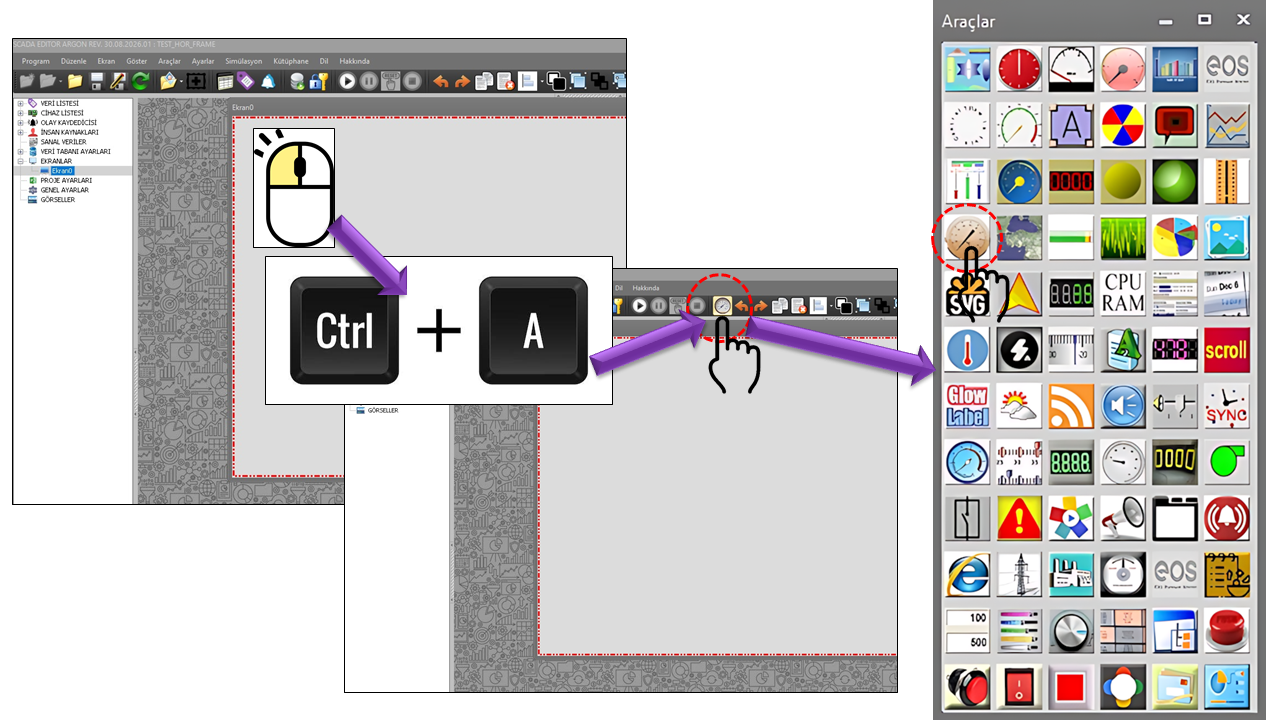
In the example provided, MANOMETER uses a circular scale configured over an approximate range of 0–100 and a pointer positioned on that scale. The pointer moves to the angular position corresponding to the connected process value, indicating the value's level on the scale.
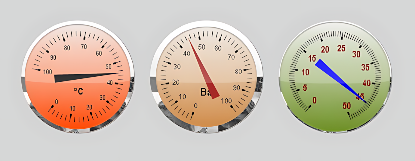
The control resembles classic analog indicators: numerical markings around the circumference, small intermediate bars, and a pointer extending outward from the center work together. This arrangement helps the operator perceive the value not only as a number but also through its geometric position on the indicator.
The primary purpose of MANOMETER is to visually monitor a value. The provided source code does not define a control function for writing values to the controller. Therefore, this control should be considered a display control intended to present the current process value clearly rather than allow the operator to make adjustments.
Minimum value → angular scale → current value → pointer position → maximum value. As the connected value changes, the pointer's angular position on the circular scale changes. This allows the operator to quickly assess which part of the defined range contains the value.
MANOMETER's fundamental visual structure is based on
converting a numerical value into an angular position on a
circular scale. The MinValue and MaxValue properties
define the boundaries of the display range, while StartAngle
determines the angle at which the scale begins.
Therefore, the pointer position in MANOMETER is not merely decorative. The angle at which the pointer is located represents the current value's corresponding position within the defined measurement range. The main advantage of the circular display is its strong support for positional perception.
The geometric placement of a scale on circular indicators is important
for readability. In MANOMETER, the starting angle can be configured using
StartAngle. In the provided source, the starting angle is
defined as 230°.
The ClockWise property determines whether the indicator's
value progression follows the clockwise direction. This setting allows
the direction in which the pointer moves from a low value to a high value
to be configured visually.
Determines the point on the circular circumference where the scale begins. It helps create suitable visual geometry for different process indicators.
Determines the direction in which the value progresses along the scale. It is an important visual parameter for creating the appearance of an analog indicator.
When the starting angle and direction are considered together, it becomes easier to design the extent of the arc used by the indicator on the screen and how it will be read.
One of the main elements that create MANOMETER's analog appearance is the
small scale bars between the numbers. The
BarsBetweenNumbers, NumberSpacing, and
Interval properties in the source code configure the scale spacing.
| Property | EOS Turkish Equivalent | Default | Description |
|---|---|---|---|
BarsBetweenNumbers |
Number of Bars Between Numbers | 5 |
Determines the number of intermediate bars used between numerical scale markings. |
NumberSpacing |
Number Spacing | 30 |
Used to configure the visual spacing between numerical scale markings. |
Interval |
Interval | 10 |
Defines the main value interval on the scale. |
BarColor |
Bar Color | Black |
Determines the color of the scale bars. |
MinValue and MaxValue define the two boundaries of
the numerical range displayed by MANOMETER. In the provided source, the
default values are defined as 0 and 100.
MinValue = 0 is the default lower limit. It defines the starting value of the indicator range.
MaxValue = 100 is the default upper limit. It defines the maximum corresponding position of the pointer on the scale.
DecimalPoint = 0 provides an integer-oriented display by default.
It is important for the scale range to match the actual operating range of the process. For example, mapping a temperature within a narrow operating range onto a very wide 0–1000 scale may reduce the effect of small changes on the pointer position. Conversely, a scale suited to the actual operating range helps the operator notice changes more easily.
The StoreMax property provides an option for separately storing
the maximum value in the indicator design. Its default value in the source
code is false.
When this property is enabled, the control is intended to support a display behavior that tracks the maximum value reached in the past. Such a feature may help evaluate the highest previously reached level alongside the current value, particularly for variable process values.
Note: Since the provided source code does not include
details of the StoreMax operating algorithm, this explanation
is based on the purpose implied by the property name and its default value
as defined in the source.
Two color parameters are particularly important to MANOMETER's appearance: the color of the scale bars and the pointer color. In the provided example, both are defined as black.
| Property | EOS Turkish Equivalent | Default | Description |
|---|---|---|---|
BarColor |
Bar Color | Black |
Determines the color of the markings on the circular scale. |
ArrowColor |
Arrow Color | Black |
Determines the color of the pointer indicating the current value. |
UCBackColor |
Control Background Color | Peru |
Determines the control's base background color. |
UCForeColor |
Control Foreground Color | Black |
Determines the control's base text color. |
BorderWidth |
Border Width | 6 |
Determines the width of the border surrounding the control. |
Rather than displaying only a scale and pointer, identifying the name and
unit of the physical quantity being displayed on the screen provides useful
context for the operator. The MANOMETER source code includes the
TextDescription and TextUnit properties for this purpose.
TextDescription is intended to configure text describing
the process information represented by the indicator.
TextUnit is used to define the physical unit of the displayed
value. The default example in the source is °C.
When the value, unit, scale, and pointer are presented together, the operator can more quickly understand which process variable the indicator represents.
Circular analog indicators are commonly used on industrial HMI/SCADA screens to provide a quick and intuitive visual assessment of continuously changing numerical values. Pointer movement visually represents the connected numerical value on a circular scale. This allows the operator to assess the current position and level of the value within the scale at a glance. Creating visual zones for different value ranges on the scale can help distinguish normal operation, warning, and critical levels more easily.
Monitoring pressure values using an appearance similar to an analog pressure gauge. This can be particularly useful for quickly assessing the position of a pressure value within a defined operating range.
Quickly monitoring temperature values using the scale and pointer. Displaying the unit alongside the value makes the meaning of the indication clearer.
Visually monitoring continuously changing values, such as tank level, flow, or flow rate, on a circular scale.
Presenting analog process variables, such as motor speed, equipment operating values, or similar quantities, using a classic indicator appearance.
Displaying the position of voltage, current, power, and similar analog quantities within a defined range.
Presenting percentage-based or range-based performance values in a classic circular gauge format. Similar gauge controls are used in industrial HMI systems to support quick perception of performance indicators.
MANOMETER's main advantage is not that it provides more data than other indicator types, but that it expresses the same data using a different visual language. Therefore, the choice can be based on how the process information should be perceived.
MANOMETER may be preferred when the angular position of the value and the appearance of an analog measuring instrument are important.
A linear indicator may be preferable when the value's position along a straight scale is more intuitive to read.
When the exact numerical value is the primary information required by the operator, a direct numerical display may be a more suitable visual approach.
The same process value can be displayed using different user controls. MANOMETER can be considered for screens where the analog indicator appearance, the positional information provided by the pointer, and the circular scale are expected to be more quickly perceived by the operator.
The main properties defined in the provided MANOMETER source code are listed below. The Turkish equivalents are presented according to the EOS terminology dictionary.
| Property | EOS Turkish Equivalent | Default | Description |
|---|---|---|---|
UCType |
Control Type | MANOMETER |
Defines the type of the user control. |
UpdateInterval |
Update Interval | 1000 ms |
Determines the control's update interval. |
DecimalPoint |
Decimal Places | 0 |
Determines the number of decimal places used in the numerical display. |
UCBackColor |
Control Background Color | Peru |
Determines the control's base background color. |
UCForeColor |
Control Foreground Color | Black |
Determines the control's base text color. |
UCFont |
Control Font | Arial Narrow, 8.25 pt |
Determines the control's base font. |
BorderWidth |
Border Width | 6 |
Determines the width of the border structure. |
TextDescription |
Text Description | "" |
Defines text describing the displayed process information. |
TextUnit |
Text Unit | °C |
Defines the unit of the displayed physical quantity. |
ClockWise |
Clockwise Direction | true |
Determines whether the scale progresses in the clockwise direction. |
MinValue |
Minimum Value | 0 |
Defines the lower limit of the display range. |
MaxValue |
Maximum Value | 100 |
Defines the upper limit of the display range. |
StoreMax |
Store Maximum | false |
Defines the option for separately tracking the maximum value. |
StartAngle |
Starting Angle | 230° |
Defines the starting angle of the circular scale. |
BarsBetweenNumbers |
Number of Bars Between Numbers | 5 |
Defines the number of intermediate scale bars between numbers. |
NumberSpacing |
Number Spacing | 30 |
Defines the spacing between numerical scale markings. |
Interval |
Interval | 10 |
Defines the scale interval. |
BarColor |
Bar Color | Black |
Determines the color of the scale bars. |
ArrowColor |
Arrow Color | Black |
Determines the color of the pointer/arrow indicator. |
A circular indicator is a powerful visual tool for quickly perceiving a value. However, when precise numerical decisions are required, the exact value can also be presented numerically. This provides both positional perception and precise numerical information.
MANOMETER is a SCADA user control that presents numerical process values using a circular scale and a moving pointer resembling classic analog measuring instruments. Its minimum and maximum value range, starting angle, clockwise direction, scale interval, number of intermediate bars, colors, unit, and descriptive text allow it to be adapted to different process variables.
The control's main strength lies in presenting a numerical value to the operator not merely as a number, but together with its angular position on the scale. Therefore, alongside linear indicators, numerical displays, or other circular indicators, it can be considered an alternative visual solution, particularly on SCADA/HMI screens where a classic analog indicator appearance is preferred.
MANOMETER = Numerical process value + circular scale + pointer position + range configuration + analog display.

Free Software Download Center
Software for industrial data collection, monitoring, and analysis.

Technical Support
Software documentation, sample code, and practical technical information.
You can contact us regarding EOS software, technical documentation, or industrial data communication.