
Free Software Download Center
Software for industrial data collection, monitoring, and analysis.
NUMERIC DIGITAL INDICATOR • NUMERICAL VALUE DISPLAY ENGINE • VISUAL DIGITAL INDICATOR
NUMERIC DIGITAL INDICATOR is a comprehensive numeric digital indicator engine designed to display process and system data numerically. Rather than using a single fixed display format, it allows you to create different frame styles, color transitions, rounded corners, and LED segment appearances.
The engine's primary approach is to let you design not only how a numerical value is displayed as text, but also its visual appearance on the screen. This allows the same data to be presented as a simple digital value, a framed indicator, a bright LED display, or a 7- or 14-segment digital display.

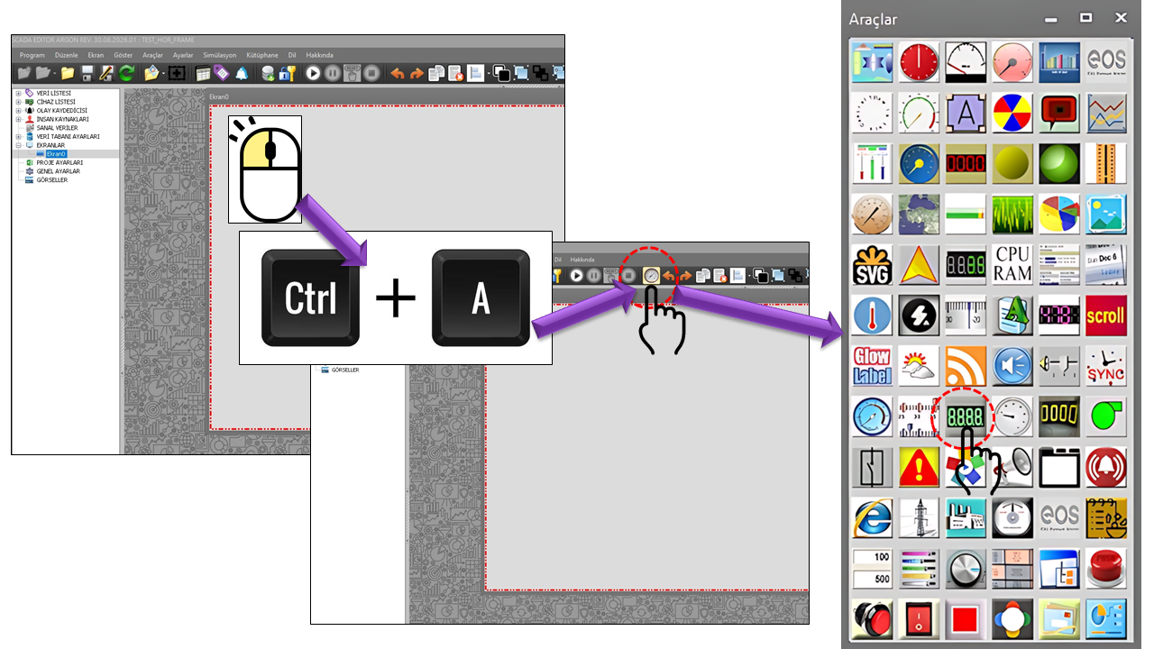
The NUMERICAL DIGITAL INDICATOR is a base indicator engine designed to create numerical digital indicators with different visual characteristics. The control is built around two separate collections: BASEUI_NUMFRAME_COLLECTION and BASEUI_LED_COLLECTION.
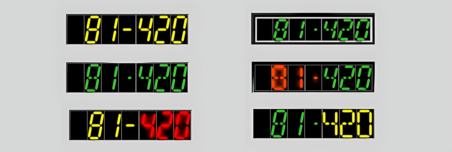
The first collection defines the geometric and visual structure of the indicator frame, while the second determines how the numerical value is displayed through LED segments. By combining these two structures, a wide variety of numerical display designs can be created within the same control.
The strength of the NUMERICAL DIGITAL INDICATOR lies in its ability to configure the fundamental components of the display individually, rather than presenting numerical values as a single predefined design. Frame position and size, outline, primary colors, gradient, corner rounding, and frame connections are managed separately from properties such as the number of LED segments, LED color, brightness, gradient, border, and shadow.
BASEUI_NUMFRAME_COLLECTION
NUMERICAL FRAME
Forms the geometric and visual foundation of the numerical display area. The frame's position, size, outline style, colors, gradient structure, and rounded-corner properties are defined through this collection.
BASEUI_LED_COLLECTION
LED SEGMENT
Creates the LED segment appearance of the numerical value. Either 7 or 14 segments can be selected; the LED background, primary color, brightness, gradient, border, and shadow can also be configured independently.
The NUMERICAL DIGITAL INDICATOR should not be thought of merely as a "numerical text box." The frame layer defines the indicator's external appearance, while the LED layer creates the digital character of the numerical value. This separation makes it easier to prepare different visual presentations for the same data.
The numerical frame collection determines the physical placement of the display area on the screen and its fundamental visual design. Since multiple numerical frames can be defined within a single user control, different values can be presented in different visual areas within the same control.
| Property | Type | Description | Default |
|---|---|---|---|
_NumframeDataName |
string | Defines the data name associated with the numerical frame. | "" |
_FrameLocation |
Point | Determines the frame's position within the control. | (0, 0) |
_FrameSize |
Size | Determines the width and height of the numerical frame. | 200 × 50 |
_Outline |
NFAnahatTur | Determines the frame's outline appearance. | None |
_CenterColor |
Color | Determines the frame's center color. | SlateBlue |
_NFEndColor |
Color | Determines the frame's ending color. | DarkBlue |
_FillGradientType |
NFGradyanTuru | Determines the frame's color transition style. | Verticalcenter |
_RoundedOff |
bool | Determines whether the frame's corners are rounded. | false |
_RoundedValue |
int | Determines the rounded-corner value. | 1 |
_FrameWidth |
int | Determines the frame width. | 1 |
_NFMainColor |
Color | Determines the frame's primary color. | Black |
_ConnectedFrameID |
string | Specifies the ID of another frame associated with this frame. | "" |
The LED collection is the core component that creates the digital segment appearance of the numerical value. By combining the number of segments, LED color, background, brightness, gradient, border, and shadow properties, designs ranging from classic digital indicators to modern LED display styles can be created.
| Property | Type | Description | Default |
|---|---|---|---|
_NumberOfSegments |
NFBolutSayisi | Determines whether numerical characters use a 7-segment or 14-segment structure. | Fourteen |
_LedBackColor |
Color | Determines the background color of the LED display area. | Black |
_BackOpacity |
int | Determines the opacity of the LED background. | 0 |
_FontThickness |
float | Determines the drawing thickness of the LED characters. | 4 |
_LCMainColor |
Color | Determines the primary color of the LED segments. | LimeGreen |
_EnableBorder |
bool | Enables or disables the border around the LED display. | true |
_BorderColor |
Color | Determines the LED border color. | Black |
_EnableGlare |
bool | Enables or disables the glow effect in the LED display. | true |
_EnableGradient |
bool | Enables or disables the LED color gradient. | false |
_LCEndColor |
Color | Determines the ending color of the LED gradient. | Black |
_GradientType |
NFGradyanTuru | Determines the direction and style of the LED gradient. | Verticalcenter |
_DisplayShadow |
bool | Determines whether a shadow effect is displayed in the LED display. | false |
_ShadowOffset |
int | Determines the shadow offset. | 3 |
_ShadowPosition |
NFGolgeKonum | Determines how the shadow is positioned. | Slide |
_ConnectedFrameID |
string | Specifies the ID of the frame associated with the LED collection. | "" |
The option sets used in the NUMERICAL DIGITAL INDICATOR determine the fundamental characteristics of the display. Since these selections directly affect the indicator design, they can also be used when creating predefined indicator templates for the library.
Seven — 7 segmentsFourteen — 14 segmentsCenter — CenterDiagonalleft — Diagonal LeftDiagonalright — Diagonal RightHorizontalcenter — Horizontal CenterLeftRight — Left to RightNone — NoneSolid — SolidTopbottom — Top to BottomVerticalcenter — Vertical CenterNormal — NormalSlide — SlidingThe NUMERICAL DIGITAL INDICATOR is a comprehensive numerical display engine that allows the entire display area to be visually designed, rather than simply presenting numerical values as text. Features such as the frame structure, colors, gradient transitions, LED segment style, glow, and shadow can be configured independently. This allows the same numerical data to be presented with different visual characteristics suited to the process screen design and the operator's readability requirements.
Defines the boundaries of the numerical area and its overall visual character.
Different indicator themes can be created using primary, center, and ending colors.
Color transitions create richer digital display appearances than flat-color designs.
Seven- or 14-segment structures can be used to create classic and advanced digital character styles.
A glow effect can make LED characters appear illuminated and more prominent.
Shadow and offset properties can change the perceived depth of the indicator on the screen.
To display a process temperature, a dark frame, a high-contrast LED color, and a 14-segment structure could be selected. For a simpler value, such as a counter or production quantity, a frame with less visual intensity and a 7-segment display could be preferred.
Numerical digital indicators are used on operator screens when measurement values need to be read quickly. In industrial processes, many different values, such as temperature, pressure, flow rate, level, speed, current, voltage, energy, counter readings, and production quantities, can be presented numerically. Technical HMI design guidelines also emphasize the importance of displaying numerical values with appropriate resolution, engineering units, and readable fonts.
A numerical value alone may not provide sufficient context, particularly for rapidly changing analog processes. Therefore, the NUMERICAL DIGITAL INDICATOR can be considered a compact, readable numerical display layer that can be used alongside other visual indicators on the same screen when necessary. The numerical value provides the operator with precise measurement information, while other graphical indicators can support an understanding of the overall process state.
The collection-based structure of the NUMERICAL DIGITAL INDICATOR is suitable for creating predefined indicator templates for later reuse. For example, the same underlying engine can be used to prepare different visual templates for temperature indicators, pressure indicators, counters, production quantities, or energy values.
The size of the NUMERICAL DIGITAL INDICATOR user control cannot be increased or decreased by dragging it with the mouse. Therefore, the exact width and height of the area in which the control will be used must be determined before placing it on the SCADA screen.
Setting the FrameSize value correctly from the outset is especially important for the readability of numerical LED characters, ensuring that segments fit within the control area, and preserving the screen layout at different resolutions.
The actual size of the control on the target screen should also be considered when adding it to the template library.
| Property | Value | Description |
|---|---|---|
UCType |
NUMERICAL DIGITAL INDICATOR | Specifies the type of the user control. |
UpdateInterval |
1000 ms | Specifies the control's default update interval. |
DecimalPoint |
0 | Specifies the default number of decimal places for the numerical value. |
UCBackColor |
Transparent | Specifies the control's background color. |
UCForeColor |
Black | Specifies the control's text color. |
UCFont |
Arial Narrow, 8.25 | Specifies the control's default font. |
GROUPID |
string | Contains the control's group ID. |
_NumericFrameCollection |
BASEUI_NUMFRAME_COLLECTION[] | Contains the numerical frame collections. |
_DigitalSegments |
BASEUI_LED_COLLECTION[] | Contains the digital LED segment collections. |
In industrial HMI applications, numerical displays are used to present process values such as temperature directly as numbers and to read values such as counter readings and production quantities. For numerical displays, it is recommended to consider the engineering unit, appropriate decimal resolution, and font readability.
Segment-based displays can be used to bring the characteristics of traditional digital screens to HMI applications. A 7-segment structure provides a simple appearance for numerical characters, while more advanced segment structures can increase the variety of visual character styles.
The fundamental strength of the NUMERICAL DIGITAL INDICATOR is that it does not restrict numerical display to a single predefined appearance. The display area can be designed using the frame collection, while the appearance of the numerical characters can be customized separately through the LED collection.
This structure provides a broad design range, from simple numerical displays to illuminated LED screens and from classic 7-segment digital indicators to more advanced 14-segment character structures. For this reason, the NUMERICAL DIGITAL INDICATOR can be considered a general-purpose numerical digital indicator engine that can be reused repeatedly in the template library.
Free Software Download Center
Software for industrial data collection, monitoring, and analysis.

Technical Support
Software documentation, sample code, and practical technical information.
You can contact us regarding EOS software, technical documentation, or industrial data communication.