Circular Analog Scale
The process value is represented on a circular dial whose start and end angles can be configured.
OSG_ROUND • ANALOG PROCESS DISPLAY • NEEDLE-BASED CIRCULAR SCALE
CIRCULAR INDICATOR (OSG_ROUND) is a user control designed to display analog process values on a traditional needle-based dial. The circular scale, adjustable tick lengths, and configurable needle position allow operators to monitor a value in relation to its position on the scale.
The needle color and length, scale start and end angles, tick frequency, center and surrounding colors, and frame options can all be configured independently. This allows the same control to be used with simple or prominent dial designs that suit different process screens.

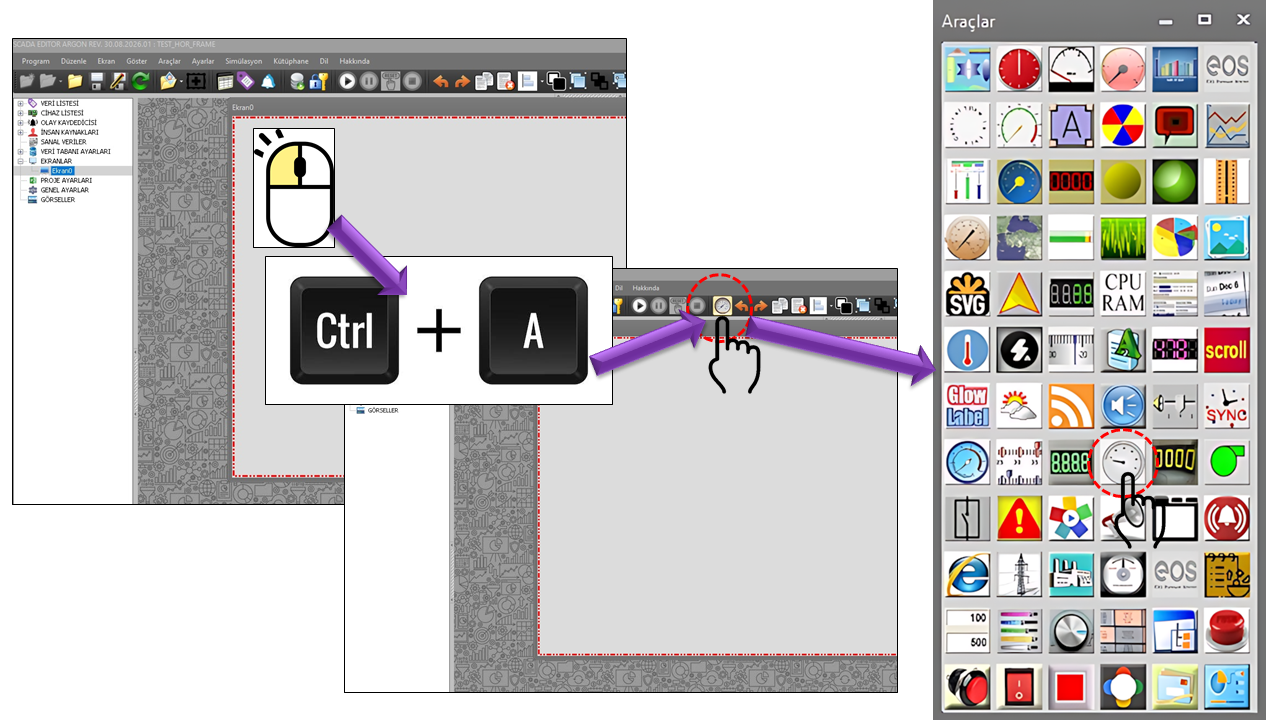
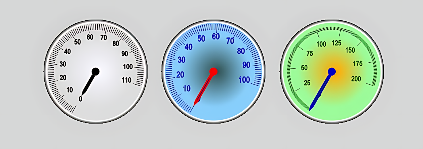
ROUND GAUGE (OSG_ROUND) visualizes a process value through the position of a needle on a circular scale rather than displaying it solely as a number. The example provided by the user features a light-colored dial, circumferential markings, numerical scale labels, a black needle, and a metallic-looking outer frame. This approach is particularly suitable for operators who need to quickly assess the position of a value within its operating range.
The process value is represented on a circular dial whose start and end angles can be configured.
The needle's visibility, length, color, and line appearance can be configured independently.
The lengths, frequency, colors, and offset values of major and alternate markings can be configured.
Different visual themes can be created using the center, surrounding area, trim, and needle colors.
Numerical scale labels can be shown or hidden as needed, and their positions can be adjusted.
The scale arc can be adapted to different dial layouts by adjusting its start and end angles.
The control focuses on the circular scale and needle. Since alarm thresholds, colored value zones, and a numerical value box are not defined among the provided properties, these functions are not presented as existing capabilities of the control.
The dial of ROUND GAUGE (OSG_ROUND) can be customized through its center and surrounding colors, outer trim line, needle, and scale markings. In particular, using light and dark tones together helps distinguish the markings and needle from the background.
The center and surrounding tones of the dial are configured using CenterColor and SurroundColor.
NeedleColor, NeedleLength, DisplayNeedle, and StrokeNeedle determine the needle's appearance.
TicksArcStart and TicksArcEnd define the angular range occupied by the scale on the circle.
The lengths, frequencies, offsets, and colors of major and alternate markings can be configured.
Labels can be enabled or disabled using DisplayTickText and positioned using TickTextOffset.
The outer appearance is completed by configuring the frame style and using TrimColor and TrimWidth.
The needle is the primary visual component that indicates the position of the current process value on the circular gauge. Scale markings help users understand the approximate value position and read it together with the labels.
| Property | English Equivalent | Default | Description |
|---|---|---|---|
PointerType |
Needle Type | Normal | Normal is the only needle type in the provided set of options. |
NeedleColor |
Needle Color | Black | Determines the color of the needle. |
NeedleLength |
Needle Length | 50 | Determines the length of the needle. |
DisplayNeedle |
Display Needle | true | Controls the visibility of the needle. |
StrokeNeedle |
Needle Line | false | Specifies the option for displaying the needle as a line. |
TickAlternateLineLength |
Alternate Marking Length | 15 | The length of alternate scale lines. |
TickLineLength |
Marking Line Length | 10 | The length of the primary scale lines. |
TickFrequency |
Marking Frequency | 10 | Determines the frequency of scale markings. |
TickLineOffset |
Marking Line Offset | 5 | Determines the positional offset of the markings. |
TicksColor |
Scale Marking Color | Black | Determines the color of the scale lines. |
TicksArcStart |
Scale Start Angle | 120 | The starting angle of the scale arc. |
TicksArcEnd |
Scale End Angle | 300 | The ending angle of the scale arc. |
DisplayTickText |
Display Scale Labels | true | Controls the visibility of numerical scale labels. |
TickTextOffset |
Scale Label Offset | 10 | Determines the position of the scale labels. |
In the default configuration, the scale start angle is 120°, the end angle is 300°, the marking frequency is 10, and the scale labels are visible. The angle values can be changed to create different arc layouts suited to the dial design.
Circular needle gauges help operators monitor a process value by showing its position within a defined scale range. Industrial HMI documentation describes these types of gauges as visualizing analog values through a needle and notes that they can be used to monitor variables such as speed. OSG_ROUND can also be used on various industrial screens following the same general display approach.
Monitoring the temperatures of furnaces, boilers, machinery, and process lines on an analog dial.
Displaying line, tank, compressor, or pump pressure through the needle position.
Monitoring the speed or rotational speed values of motors and rotating equipment.
Visualizing flow measurements on a defined scale.
Allowing the operator to monitor the current value together with its position within the operating range.
Presenting multiple process variables together using separate gauges.
OSG_ROUND emphasizes the position of the value on the scale. On screens where precise numerical readings are also important, it can be used together with a separate numerical indicator. This makes it possible to display both the current number and its position on the scale on the same screen.
The control's general configuration is managed through the update interval, decimal places, primary colors, font, frame, and dial colors. The values below are the initial settings in the shared source code.
| Property | English Equivalent | Default |
|---|---|---|
UCType |
Control Type | OSG_ROUND |
UpdateInterval |
Update Interval | 1000 ms |
DecimalPoint |
Decimal Places | 0 |
UCBackColor |
Control Background Color | Transparent |
UCForeColor |
Control Text Color | Black |
UCFont |
Control Font | Arial Narrow, 8.25 |
BorderStyle |
Border Style | None |
CenterColor |
Center Color | GhostWhite |
SurroundColor |
Surrounding Color | Gainsboro |
TrimColor |
Trim Color | Black |
TrimWidth |
Trim Width | 6 |
The shared code for OSG_ROUND defines options for the needle type and frame type. The needle type currently has only one option, while the frame appearance can be configured in three different styles.
Normal — NormalNone — NoneFixedsingle — Fixed SingleFixed3d — Fixed 3DWhen designing the dial, it is important to ensure sufficient contrast between the needle, scale markings, and numerical labels. Since using too many markings can reduce readability on small screens, the marking frequency and label offset should be adjusted to suit the target screen size.
On a motor speed gauge, a black needle and a light-colored dial can be used to emphasize the speed's position on the scale. A fixed three-dimensional frame can be selected when a more pronounced instrument appearance is desired. When multiple gauges are used on the same screen, maintaining consistent scale markings and color schemes helps ensure visual consistency.
The shared properties do not include minimum and maximum value definitions. The measurement range and how the process data is mapped to the scale must be verified separately in the control's relevant data configuration. The angle and marking properties described here define the visual layout of the display.
Industrial HMI documentation describes circular gauges as visual objects that represent the value of a connected analog variable on a dial and needle. Arc angle, major and intermediate markings, needle length, and color are important elements of the general analog gauge design approach. These sources support general industrial usage and display principles, not the internal drawing algorithm of OSG_ROUND itself.
OSG_ROUND can be used to display analog process values on a circular dial through its needle, scale arc, markings, numerical labels, colors, and frame options. Among the available circular gauge alternatives, it provides a distinct design option for screens that favor a classic needle-based appearance.

Free Software Download Center
Software for industrial data collection, monitoring, and analysis.

Technical Support
Software documentation, sample code, and practical technical information.
You can contact us regarding EOS software, technical documentation, or industrial data communication.