PIPE ANIMATION
Visually indicates the direction and movement of flow; the flow shape, direction, spacing, size, and animation timing can be configured.
PIPES_MOTORS • PIPE AND MOTOR CONTROL • LIVE ANIMATION
ANIMATED PIPES AND MOTORS is a user control used to visually represent process flow and the operating status of rotating equipment on SCADA screens. The control supports two basic display types: animated pipes and animated motors.
For pipes, the flow direction, shape, spacing, speed, and starting boundary can be configured. For motors, configurable properties include the fan appearance, colors, shadow, base, and connection points. With a transparent background, the control can also be used as a moving overlay placed on top of a static pipe, motor, pump, or plant illustration.

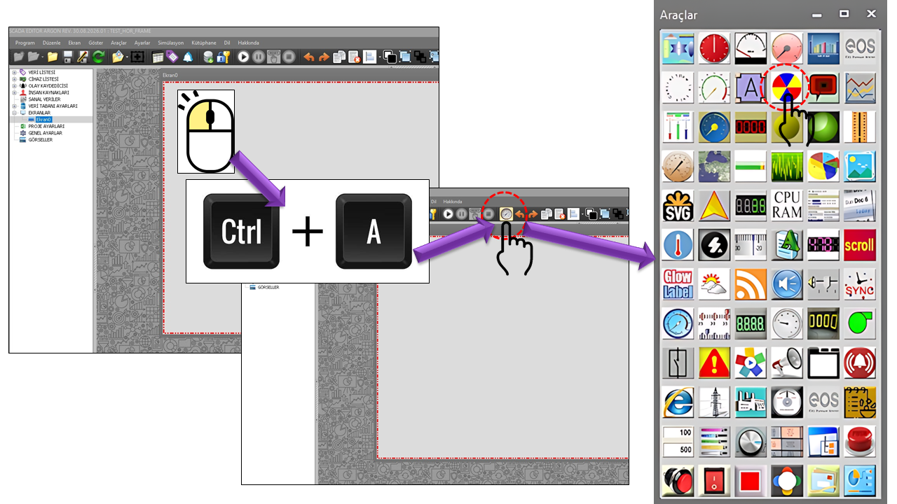
ANIMATED PIPES AND MOTORS (PIPES_MOTORS) is a graphical user control designed to communicate the operating status of process equipment through movement, rather than displaying it only as a static image on SCADA/HMI screens. The primary purpose of this control is to enable operators to quickly recognize, from visual movement on the screen, whether flow is occurring in a process line or rotating equipment is running.
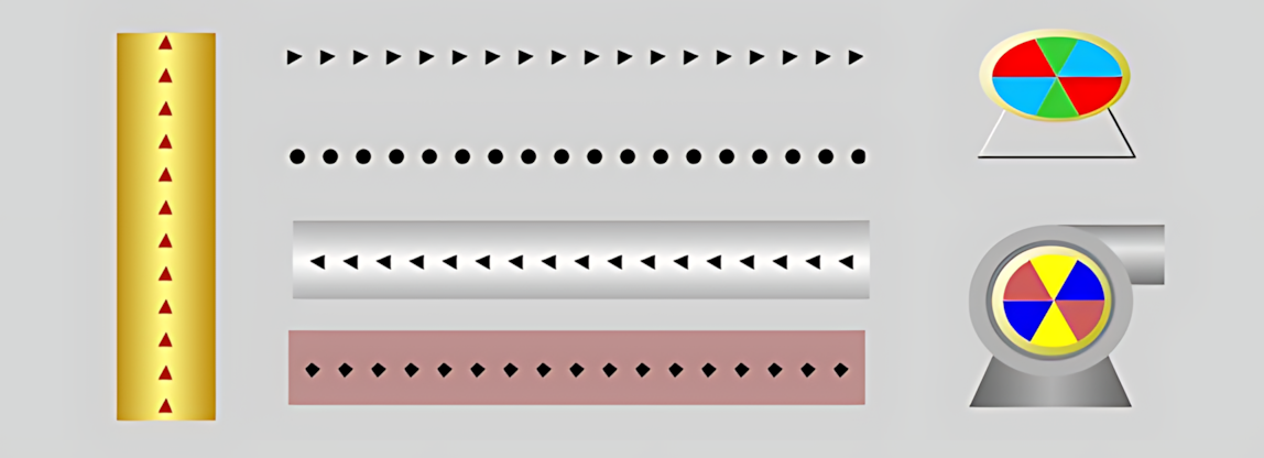
The control combines two distinct visual approaches within a single structure: Animated Pipe and Animated Motor. When a pipe is selected, flow indicators move along the pipe; when a motor is selected, the motor's fan/rotor section rotates. These two configurations allow the same visual language to be used in different parts of a process.
Using UCBackColor = Transparent helps PIPES_MOTORS blend into the background. This makes it possible to use only the animation layer representing movement over a detailed static pipe, motor, pump, or plant image prepared for the SCADA screen. This approach is particularly useful for creating realistic process mimic screens.
Visually indicates the direction and movement of flow; the flow shape, direction, spacing, size, and animation timing can be configured.
Animates the rotating section of a motor; the visual appearance can be enhanced with fan colors, a frame, shadow, base, and connection ports.
When PMGostergeTuru.Animatedpipe is selected, the control creates moving flow indicators along the process line.
The shape of the flow indicators can be configured using GNAkisSekli, their direction using GNAkisYonu, the pipe orientation using
GNAciBilgisi, and the pipe appearance using GNBoruStili.
Animatedpipe.Movement in PIPES_MOTORS is a visual representation of the process. If it is intended to represent actual flow information, starting/stopping the animation and determining its direction must be linked to appropriate SCADA data or logic. Particularly in lines where reverse flow is possible, Animation Type and Animation Direction should be evaluated together.
When PMGostergeTuru.Animatedmotor is selected, the control displays an animated fan structure representing the rotating section of the motor. A visual motor symbol can be created using three fan colors, the frame color, and shadow depth. The motor base and connection ports can also be displayed if desired.
Instead of drawing an entire realistic motor/pump symbol using animation, the static equipment image on the screen can be retained as the background, with PIPES_MOTORS placed only over the rotating fan section. This preserves the equipment housing, flanges, pipe connections, cables, and other details in the static image, while the operating status is communicated through the rotating section alone.
Motor animation representing the operation of a pump, fan, compressor, or similar rotating equipment helps visually distinguish its operating status through movement while preserving the equipment's position on the process mimic screen. To display the actual operating state, the animation must be appropriately linked to the process data being used.
The general animation behavior of PIPES_MOTORS is defined by AnimationType, while its visual color scheme is defined by
ColorScheme. These options allow the pipe and motor displays to be adapted to the screen design.
| Property | Option Set | Description |
|---|---|---|
PMGostergeTuru |
Animatedpipe / Animatedmotor |
Determines whether the control operates as an animated pipe or an animated motor. |
PMAnimasyonTuru |
Onewayanimated / Bidirectionalanimated |
Selects whether the animation operates in one direction or in both directions. |
GNRenkDuzeni |
Purple / Green / None |
Determines the color scheme to be used by the control. |
PurplePurple color schemeGreenGreen color schemeNoneCustom/default color approachThe control's basic operating and appearance properties are defined by the following parameters.
| Property | EOS Turkish Equivalent | Default | Purpose | Where It Is Used |
|---|---|---|---|---|
UCType |
Control Type | PIPES_MOTORS |
Defines the type of the user control. | In the basic definition of the pipe and motor animation control. |
UpdateInterval |
Update Interval | 1000 ms |
Determines the control's update interval. | For periodic data updates on the SCADA screen. |
DecimalPoint |
Decimal Places | 0 |
Determines the number of decimal places used when displaying numerical values. | In designs where the control is associated with numerical data. |
UCBackColor |
Control Background Color | Transparent |
Determines the control's background; transparency supports layered graphic design. | On screens where animation is placed over a static equipment image. |
UCForeColor |
Control Foreground Color | Black |
Determines the control's primary foreground color. | In designs that contain control text. |
UCFont |
Control Font | Arial Narrow, 8.25 pt, Bold |
Determines the control's font settings. | For the appearance of text displayed on the control. |
ColorScheme |
Color Scheme | None |
Determines the color scheme of the pipe or motor animation. | For consistency with equipment color standards on the SCADA screen. |
AutoSize |
Auto Size | false |
Determines the control's sizing behavior. | When aligning the animation layer with a static equipment image. |
BorderColor |
Border Color | FromArgb(234,218,245) |
Determines the color of the control's border. | For the visual frame around the animation area. |
BorderWidth |
Border Width | 6 |
Determines the border thickness. | For adjusting the visual boundary of the motor/pipe control. |
The pipe animation's geometry, the appearance of flow indicators, and the style of the pipe body are configured using these properties.
| Property | EOS Turkish Equivalent | Default | Purpose |
|---|---|---|---|
PipeRotation |
Pipe Rotation | Zerodegrees |
Sets the pipe orientation to 0°, 90°, 180°, or 270°. |
FlowStyle |
Flow Style | Triangle |
Determines the geometry of the indicator representing flow. |
AnimationDirection |
Animation Direction | Forward |
Determines the direction in which the flow indicators move. |
TubeStyle |
Pipe Style | Cylinder |
Determines whether the pipe body appears cylindrical, flat, or empty. |
FlowSpacing |
Flow Spacing | 8 |
Determines the spacing between consecutive flow indicators. |
| Option Set | English |
|---|---|
Zerodegrees |
0 Degrees |
Ninthydegrees |
90 Degrees |
HundredEightydegrees |
180 Degrees |
Twohundredseventhydegrees |
270 Degrees |
| Option Set | English |
|---|---|
Circle |
Circle |
Square |
Square |
Diamond |
Diamond |
Triangle |
Triangle |
| Option Set | English |
|---|---|
Forward |
Forward |
Backward |
Backward |
| Option Set | English |
|---|---|
Cylinder |
Cylinder |
Flat |
Flat |
None |
None |
This group contains the timing, startup conditions, visibility, and dynamic behavior of the flow animation.
| Property | EOS Turkish Equivalent | Default | Purpose |
|---|---|---|---|
AnimationInterval |
Animation Interval | 100 ms |
Determines the animation timing interval. |
AnimationStartLimit |
Animation Start Limit | 2 |
Determines the startup threshold used to initiate the animation. |
FlowSize |
Flow Size | 7 |
Determines the visual size of the flow indicators. |
FlowHideWhenOff |
Hide Flow When Off | false |
Determines the visibility behavior of the flow when it is off. |
DynamicAnimation |
Dynamic Animation | false |
Enables configuration of the animation using dynamic lower and upper limits. |
DynamicLowLimit |
Dynamic Lower Limit | 0 |
Determines the lower limit for dynamic animation. |
DynamicHighLimit |
Dynamic Upper Limit | 100 |
Determines the upper limit for dynamic animation. |
The visual rhythm of the animation is not the process value itself. If movement on the operator screen represents a measured value, this relationship must be clearly defined; screen performance and readability should be considered together, especially for high-speed animations.
The visual appearance of the motor animation is created using fan colors, the frame, shadow, and the base/connection ports.
| Property | EOS Turkish Equivalent | Default | Purpose |
|---|---|---|---|
FanColor1 |
Fan Color 1 | RGB(132,100,161) |
Determines the first color used in the fan appearance. |
FanColor2 |
Fan Color 2 | RGB(251,246,255) |
Determines the second color used in the fan appearance. |
FanColor3 |
Fan Color 3 | RGB(191,161,211) |
Determines the third color used in the fan appearance. |
FanBezelColor |
Fan Bezel Color | RGB(110,92,121) |
Determines the appearance of the frame/bezel surrounding the fan. |
FanShadowDepth |
Fan Shadow Depth | 3 |
Determines the shadow/depth effect in the fan appearance. |
BaseVisible |
Base Visible | false |
Determines whether the motor base is displayed. |
BaseStyle |
Base Style | Trapezoid |
Determines the geometric style of the motor base. |
PortDisplayTop |
Display Top Port | false |
Determines whether the top connection port is displayed. |
PortDisplayBottom |
Display Bottom Port | false |
Determines whether the bottom connection port is displayed. |
PortDisplayRight |
Display Right Port | false |
Determines whether the right connection port is displayed. |
PortDisplayLeft |
Display Left Port | false |
Determines whether the left connection port is displayed. |
PortStyle |
Port Style | Gradient |
Determines the visual style of the connection ports. |
| Option Set | English |
|---|---|
Trapezoid |
Trapezoid |
Feet |
Feet |
| Option Set | English |
|---|---|
Gradient |
Gradient |
Fat |
Flat |
PIPES_MOTORS is particularly useful on screens where processes are monitored through equipment and flow paths. The following examples combine the control's source-code features with common applications of SCADA/HMI graphic animations.
Displaying flow between pump stations, transfer lines, filters, and tanks using pipe animation, while distinguishing pump operating status through motor animation.
Visualizing the direction of pipelines and the operating status of equipment on process mimic screens in chemical, food, and other continuous-process industries.
Representing cooling water, lubrication, auxiliary services, and similar flows with pipe animation, and displaying the rotation of fans and motors on the equipment itself.
Monitoring fans, pumps, rotating equipment, and flow connections using animated symbols on a single HMI screen.
Using animated graphics to make the status of air/water circuits, fans, and pumps easier to recognize on mimic screens.
Creating richer process visualizations by adding a moving flow or rotor layer over static equipment drawings.
One of the main strengths of PIPES_MOTORS is that the animation does not need to recreate the entire equipment drawing. Using only the moving part over a detailed static SVG, PNG, or other graphic can enhance the visual richness of the process screen.
At a pump station, the pump housing can be prepared as a detailed static image. The motor section of PIPES_MOTORS is placed over this image to represent only the rotor/fan section. The rotor moves when the pump is operating as intended; on the pipe side, flow indicators move to visually indicate that water is flowing through the line. This allows the screen to depict the equipment realistically while communicating its operating status through movement.
| Area | Key Property | Important Options / Default |
|---|---|---|
| Control Type | UCType |
PIPES_MOTORS |
| Display | GaugeType |
Animatedpipe — Animated Pipe; Animatedmotor — Animated Motor |
| Animation Type | AnimationType |
Onewayanimated — One-Way Animation; Bidirectionalanimated — Bidirectional Animation |
| Pipe Flow | FlowStyle, AnimationDirection, FlowSpacing, FlowSize |
Triangle, Forward, 8, 7 |
| Pipe Geometry | PipeRotation, TubeStyle |
0 Degrees, Cylinder |
| Motor Appearance | FanColor1-3, FanBezelColor, FanShadowDepth |
Purple shades, 3 |
| Motor Base | BaseVisible, BaseStyle |
false, Trapezoid |
| Layered Use | UCBackColor |
Transparent |
Animation is a visual information layer that assists the operator. To verify the actual operating status of equipment, the process data and logic feeding the animation must be designed correctly. Visual movement alone should not be treated as an independent verification mechanism confirming that physical equipment is actually operating.
PIPES_MOTORS is a user control that can be used to transform SCADA screens from static equipment drawings into dynamic mimic screens that also communicate process movement.
PIPE ANIMATION emphasizes the direction and movement of flow, while MOTOR ANIMATION highlights the operating movement of rotating equipment. Thanks to its transparent background and configurable visual properties, the control can be placed over detailed static plant images as an animation layer containing only the necessary movement.
Let the static image represent physical realism, and let PIPES_MOTORS represent dynamic process information. This preserves the detailed appearance of the equipment while communicating critical conditions such as flow and rotation in a dynamic way that attracts the operator's attention.

Free Software Download Center
Software for industrial data collection, monitoring, and analysis.

Technical Support
Software documentation, sample code, and practical technical information.
You can contact us regarding EOS software, technical documentation, or industrial data communication.