Static Image
Display an image of a machine, piece of equipment, facility, symbol, or explanatory illustration on a SCADA screen.
EOS SCADA • IMAGE • DYNAMIC VISUALS • ANIMATION
IMAGE is a specialized user control that not only allows static images to be added to SCADA screens, but also enables dynamic animations by linking image sequences consisting of multiple images to process data.
When a data value meets a specified condition, the image sequence can be activated, and the images can be displayed consecutively at a defined animation speed. This makes it possible to visually animate a rotating motor, a running fan, fluid flow, machine movement, or a particular process state.

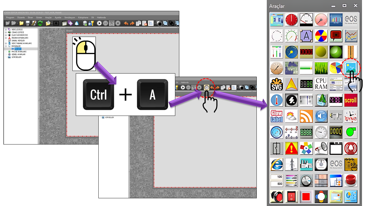
The primary purpose of the IMAGE user control is to use an image as a visual object on a SCADA screen. However, an important distinction is that, in addition to displaying a single static image, multiple image files can be defined using the IMAGE_COLLECTION[] structure, allowing these images to be used for animation.
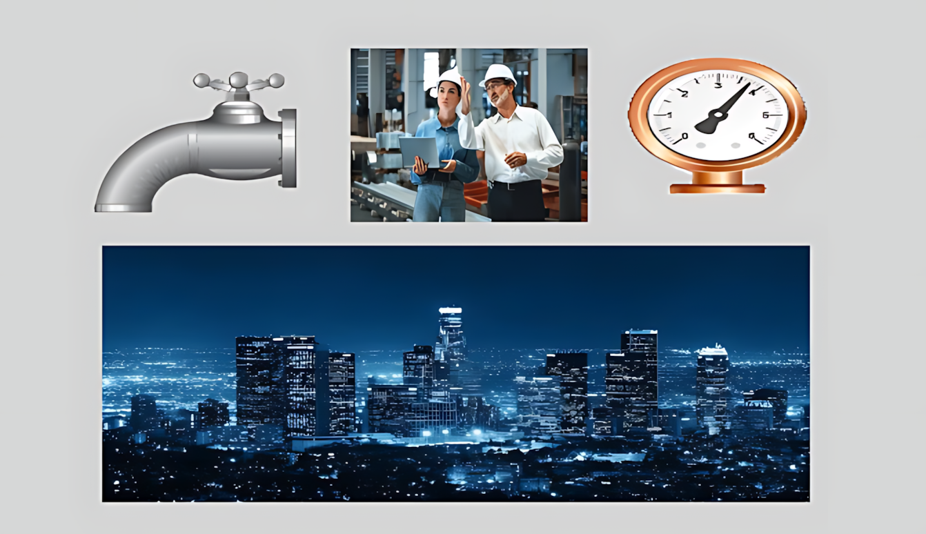
Display an image of a machine, piece of equipment, facility, symbol, or explanatory illustration on a SCADA screen.
Define different frames of a movement as separate images and use them in sequence.
Use SCADA data as a condition to start or stop an animation, or to run it within a dynamic range.
The strength of this user control lies in its ability to go far beyond simply displaying a single image. A list of image files is created using RotatingImageFiles. By displaying the images in the list in a specified order, a frame-by-frame animation is produced.
For example, 12 separate image frames can be prepared for a fan. When the operating information received from SCADA satisfies the specified condition, these 12 images can be displayed sequentially to make the fan appear to rotate. This approach can be used to visually represent pumps, fans, motors, conveyors, valve movement, flow, rotating equipment, and machine cycles.
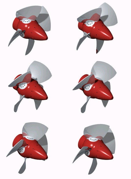
The IMAGE control does not have to use animation only as a continuously running effect. The DynamicAnimation, DynamicLowLimit, and DynamicHighLimit properties allow the animation to be associated with a data range.
Suppose the fan speed is represented by a SCADA value ranging from 0 to 100. If the dynamic animation range is configured as 20–100, the fan's visual animation can be associated with this operating range. Instead of merely indicating whether the fan is running or stopped, the control can exhibit visual behavior according to the process value.
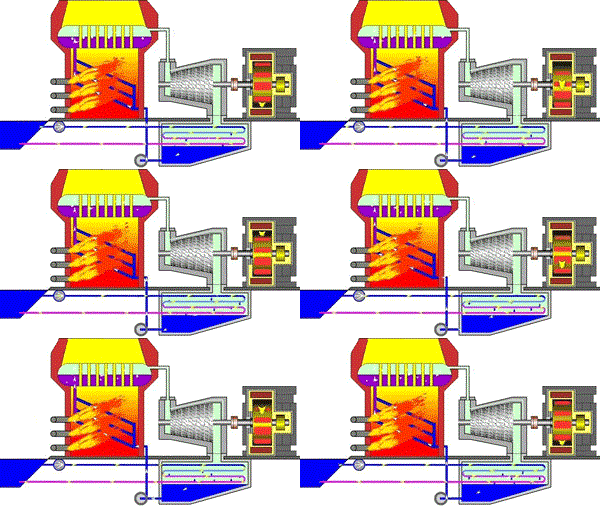
The IMAGE control is not limited to decorative graphics. It is particularly useful on screens where process conditions must be communicated to operators quickly and intuitively.
Visually represent the operating status of rotating equipment using an image sequence.
Represent pump operation or flow direction using animated images.
Display a machine's cycle steps or movements using visual frames.
Create animations for turbines, shafts, fans, mixers, and similar rotating mechanisms.
| Property | Value | Description |
|---|---|---|
| UCType | RESIM | Specifies the user control type. |
| UpdateInterval | 1000 | Specifies the control's update interval. |
| DecimalPoint | 0 | Specifies the number of decimal places. |
| UCBackColor | Transparent | Specifies the control's background color. |
| UCForeColor | Black | Specifies the control's text color. |
| UCFont | Arial Narrow, 8.25 Bold | Specifies the control's font. |
| DefaultImageFile | "" | Specifies the image file to display by default. |
| Source Property | English Equivalent | Default | Description |
|---|---|---|---|
| DefaultImageFile | Default Image File | "" | Specifies the image to display when animation is not used or in the initial view. |
| RotatingImageFiles | Rotating Image Files | IMAGE_COLLECTION[] | A collection of image files to be displayed sequentially during animation. |
| UseAnimation | Use Animation | false | Enables the image sequence to be used for animation. |
| AnimationSpeed | Animation Speed | 500 | Determines the frame transition speed in the image sequence. |
| ThrasholdValue | Threshold Value | 50 | A threshold value that can be used as an animation condition. |
| UseBorder | Use Border | false | Specifies whether a border is displayed around the control. |
| DynamicAnimation | Dynamic Animation | false | Enables animation behavior to be associated with a dynamic data range. |
| DynamicLowLimit | Dynamic Low Limit | 0 | Specifies the lower limit for dynamic animation. |
| DynamicHighLimit | Dynamic High Limit | 100 | Specifies the upper limit for dynamic animation. |
The following scenario illustrates an example configuration showing how the IMAGE control can be transformed from a static image into an animated process object.
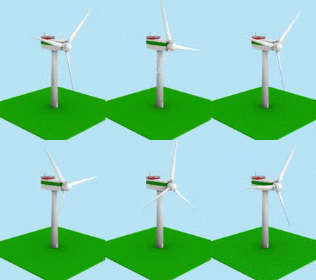
The IMAGE user control should not be regarded merely as a simple image-display object for adding static graphics to SCADA screens. When RotatingImageFiles, UseAnimation, AnimationSpeed, and the dynamic animation properties are used together, the control can become an animation object that represents process conditions through visual movement.
This approach can be used to communicate the status of motors, fans, pumps, flow, rotating mechanisms, and machine cycles to operators more intuitively. In industrial HMI/SCADA platforms, dynamically linking graphical objects to process values and using techniques such as image switching and animation are common visualization approaches. This control provides the same general approach through an image-sequence-based structure.

Free Software Download Center
Software for industrial data collection, monitoring, and analysis.

Technical Support
Software documentation, sample code, and practical technical information.
You can contact us regarding EOS software, technical documentation, or industrial data communication.