
Free Software Download Center
Software for industrial data collection, monitoring, and analysis.
EOS SCADA • SYNCHROSCOPE • SYNCHRONIZATION • USER CONTROL
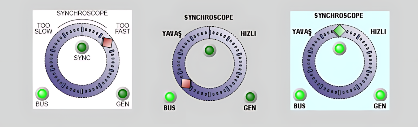
SYNCHROSCOPE is a synchronization indicator used to monitor the phase relationship between a generator and an energized busbar or grid before connecting the generator. In a conventional synchroscope, the moving indicator helps operators visually monitor the phase angle difference and frequency difference between the generator and the busbar.
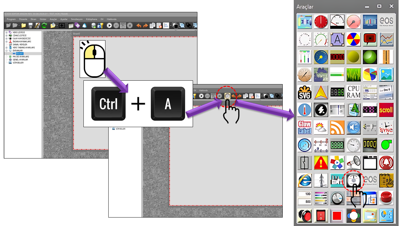
This user control in EOS SCADA can be used to represent the physical instrument symbolically on a SCADA screen. Simulation mode allows the synchronization process to be modeled visually. When connected to real field data, the control can display actual operating information using the busbar phase, generator phase, circuit breaker status, and the signal that initiates synchronization.

A synchroscope is a measuring and indicating instrument used to visually assess the synchronization conditions between two AC sources before they are connected in parallel. Manufacturer documentation describes a synchroscope as a device used to monitor the frequency difference and phase-angle difference between two generators or between a generator and the electrical grid. As the phase difference approaches zero, the indicator approaches the synchronization mark, making the appropriate synchronization instant visually apparent.
When connecting a generator in parallel with the grid, not only the phase angle but also the voltage and frequency conditions must be suitable. In synchronization systems, the operator primarily monitors the voltage difference, frequency difference (slip), and phase-angle difference, with the aim of closing the circuit breaker at the appropriate instant. A technical paper published by SEL also explains that voltage, speed/frequency, and phase-angle differences are monitored during synchronization and that the circuit breaker should be closed as close as possible to a zero-degree phase difference.
Before two electrical systems are connected in parallel, their electrical conditions must be suitable. Synchronization checks compare voltage, frequency, and phase angle. When the frequencies differ, the phase angle changes over time; therefore, the direction and speed of the synchroscope indicator provide visual information about the frequency difference between the generator and the busbar. Schneider Electric's explanation of synchronism checking also states that the phase angle rotates because of the frequency difference and that the lowest electrical stress is achieved when the connection is made close to zero phase difference.
An important feature of the SYNCHROSCOPE user control is that it is not limited to being used as a decorative symbol. The four data connections in the control's source code are intended to transfer actual field information to the user control. When these inputs are connected to appropriate SCADA tags, the control can be used as a visual HMI component in the synchronization process.
UseSimulation.An important point is that the user control itself must not be assumed to replace a protection relay or an independent synchronism-check relay. In critical field applications, synchronization permissives and circuit-breaker closing operations must be managed safely by the relevant protection and control systems. The SYNCHROSCOPE on the SCADA screen can be used to present this information visually to the operator. Manufacturer documentation also shows that, in real synchronization-control applications, the decision to close the circuit breaker is associated with synchronism checking.
To represent the actual synchroscope function meaningfully on a SCADA screen, the following four properties must be connected to appropriate field or SCADA data. These four fields are defined as string in the source code; therefore, the actual data type, value encoding, and tag address must be determined according to the SCADA data structure used in the application.
| Property | English Equivalent | Description |
|---|---|---|
DataBusPhaseMeasured |
Measured Busbar Phase | The measured phase information for the grid or reference busbar side. It represents the electrical side used as the synchroscope reference. The phase-angle information provides the basis for visually assessing the angle difference between the two sides by comparison with the generator phase. |
DataGenPhaseMeasured |
Measured Generator Phase | The measured phase information for the generator that is to be connected to the grid. When evaluated together with the busbar phase, it establishes the generator's phase position relative to the reference system. Monitoring the phase-angle difference between the generator and the busbar is one of the fundamental functions of synchroscope applications. |
DataCircuitBreakerMeasured |
Measured Circuit Breaker Value | The measured status information associated with the circuit breaker connecting the generator to the busbar. This data can help visually indicate whether the connection is open or closed, or display other status codes used by the application, on the synchronization screen. |
DataStartSignalMeasured |
Start Signal | A field or control signal associated with starting the synchronization process. In synchronization systems, a start signal can be used as an input that triggers activation of the synchronization function. |
These four data inputs are not independent indicators. DataBusPhaseMeasured and DataGenPhaseMeasured establish the phase relationship for synchronization, while DataStartSignalMeasured represents the state associated with starting the synchronization process and DataCircuitBreakerMeasured represents the status of the connecting device. This gives the control the data inputs needed to interpret the different stages of synchronization on the SCADA screen, rather than merely drawing a moving pointer.
The most characteristic synchroscope indication is the phase-angle difference. If two sources operate at different frequencies, their phase angle changes over time; as their frequencies approach one another, this movement slows down. The objective is to close the circuit breaker when the frequency and phase relationship reach a suitable point. The CIRCUTOR synchroscope documentation also explains that the frequency and phase-angle differences between two sources are monitored and that, when the difference reaches zero, the indicator settles at the synchronization mark.
Correct visual information from a synchroscope on a SCADA screen is not the same as safely closing the actual circuit breaker. In real electrical installations, voltage, frequency, phase angle, synchronism permissives, circuit-breaker status, and relevant interlocks must be evaluated together. Manufacturer documentation on synchronism checking clearly shows that the circuit-breaker closing command is associated with synchronization logic when the required conditions are met. Therefore, SYNCHROSCOPE must not be treated as an independent safety mechanism that replaces critical closing logic.
The default value _UseSimulation = true in the source code indicates that a simulation option is available, allowing the control to model synchronization behavior visually without external field data. This feature is particularly useful for training, commissioning preparation, HMI design, and demonstrating screen functionality.
This scenario does not establish a real electrical connection; it should be used only to model the visual behavior of the user control.
| Property | English Equivalent | Default | Description |
|---|---|---|---|
UCType |
Control Type | SYNCHROSCOPE |
Determines the type of the user control. |
UpdateInterval |
Update Interval | 1000 |
The interval at which the control's data and visual display are updated. |
DecimalPoint |
Decimal Places | 0 |
The decimal-place setting used for numeric displays. |
UCBackColor |
Control Background Color | White |
Determines the control's background color. |
UCForeColor |
Control Text Color | Black |
Determines the text or display color used on the control. |
UCFont |
Control Font | Arial Narrow, 8.25f |
The font and font size used by the control. |
UseSimulation |
Use Simulation | true |
Enables the control's simulation behavior instead of using real data. |
BorderStyle |
Border Style | GNCerceveTuru.None |
Determines the control's frame or border appearance. Since the details of the enumeration are not included in the supplied source code, only the default value is shown here. |
DataBusPhaseMeasured |
Measured Busbar Phase | Empty | Measured phase data from the busbar side. |
DataGenPhaseMeasured |
Measured Generator Phase | Empty | Measured phase data from the generator side. |
DataCircuitBreakerMeasured |
Measured Circuit Breaker Value | Empty | Measured status data associated with the circuit breaker. |
DataStartSignalMeasured |
Start Signal | Empty | Data representing the synchronization start signal. |
Manufacturer technical documentation and power-system synchronization references were used to describe the function of the synchroscope and the relevant synchronization conditions.
Free Software Download Center
Software for industrial data collection, monitoring, and analysis.

Technical Support
Software documentation, sample code, and practical technical information.
You can contact us regarding EOS software, technical documentation, or industrial data communication.