Base Arc
Defines the main geometry of the gauge dial. It is configured using color, start angle, sweep angle, radius, and width.
EOS SCADA • CIRCULAR GAUGE • CIRCULAR GAUGE • USER CONTROL
CIRCULAR GAUGE is a graphical user control used to display analog process values on EOS SCADA screens in the form of a traditional measuring instrument. The value is represented visually by the position of the needle on a circular scale.
The control allows elements such as the main arc, needle, major and minor tick marks, scale numbers, color ranges, labels, and background image to be configured together. The design can be adapted to different geometric display formats, including a full circle, semicircle, or quarter circle.

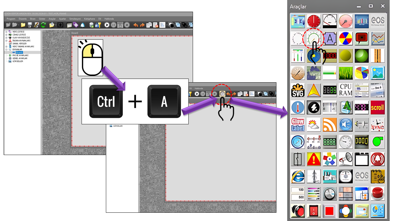
The CIRCULAR GAUGE visually presents the position of a numerical value within a defined minimum and maximum range using a dial and needle, rather than displaying the value as digits alone. This approach helps the operator quickly recognize the value's position within the normal operating range.
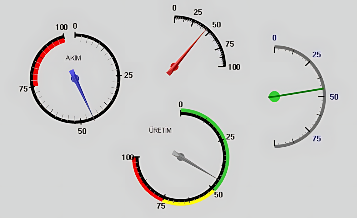
An examination of the control's source structure in EOS SCADA shows that the gauge consists of more than just a needle. The Base Arc, Needle, Scale Lines, Scale Numbers, Region Collection, and Label Collection are treated as independently configurable components.
Core concept: The CIRCULAR GAUGE makes an analog process variable readable at a glance by combining a value, scale, needle, and colored visual regions. It is therefore a useful visual tool, especially on SCADA/HMI screens where operators need to assess process conditions quickly.
Defines the main geometry of the gauge dial. It is configured using color, start angle, sweep angle, radius, and width.
The moving element that displays the current value on the dial. Its appearance is configured using color, type, width, and radius.
Intermediate, minor, and major scale lines, together with scale numbers, make it possible to read the value represented on the dial.
The CIRCULAR_REGION_COLLECTION structure can be used to highlight specific value ranges with different colors.
Text such as the process name, physical quantity, unit, or description can be displayed using LABEL_COLLECTION.
A background image can provide the visual foundation for a custom gauge design.
The following table lists the general properties and default values directly defined in the supplied source code. The English descriptions are based on the corresponding EOS SCADA terminology.
| Property | English Equivalent | Default | Description |
|---|---|---|---|
UCType |
Control Type | DAIRESEL_GOSTERGE |
Defines the EOS SCADA user control type. |
UpdateInterval |
Update Interval | 1000 ms |
Specifies the interval at which the control's data/display is updated. |
DecimalPoint |
Decimal Places | 0 |
Specifies the number of decimal places used to display numerical values. |
UCBackColor |
Control Background Color | Transparent |
Defines the control's background color. |
UCForeColor |
Control Foreground Color | White |
Defines the control's general foreground/text color. |
UCFont |
Control Font | Microsoft Sans Serif, 8.25 pt, Bold |
Defines the control's default font. |
BorderStyle |
Border Style | None |
Defines how the control's border is displayed. |
The GNCerceveTuru options defined in the source code are:
The Base Arc defines the main dial geometry on which the scale and needle operate. Different dial shapes can be created by adjusting the start angle, sweep angle, radius, and width together.
| Property | English Equivalent | Default | Usage |
|---|---|---|---|
BaseArcColor |
Base Arc Color | Gray |
Defines the color of the dial's base arc. |
BaseArcStart |
Base Arc Start Angle | 270° |
Defines the starting angle of the base arc. |
BaseArcSweep |
Base Arc Sweep | 90° |
Defines the angular sweep of the base arc. |
BaseArcRadius |
Base Arc Radius | 80 |
Defines the radius of the base arc. |
BaseArcWidth |
Base Arc Width | 2 |
Defines the thickness of the base arc line. |
Center |
Center | Point(15, 100) |
Defines the center position of the gauge geometry. |
Geometric flexibility: The base arc's start and sweep values play a key role in determining which portion of the gauge geometry is used. This allows the same user control to be adapted to different screen layouts, such as full-circle, semicircular, or quarter-circle gauges.
The needle is the visual representation of the analog value on the dial. In the supplied source code, two needle colors, the needle type, width, and radius can be configured.
| Property | English Equivalent | Default | Description |
|---|---|---|---|
MinValue |
Minimum Value | 0 |
Defines the lower limit of the gauge scale. |
MaxValue |
Maximum Value | 100 |
Defines the upper limit of the gauge scale. |
NeedleColor1 |
Needle Color 1 | Gray |
The first needle color, selected using the DGRenkTuru enum. |
NeedleColor2 |
Needle Color 2 | DimGray |
Defines the needle's second color component. |
NeedleType |
Needle Type | Advance |
Defines the needle shape using the DGIgneTuru enum. |
NeedleWidth |
Needle Width | 2 |
Defines the needle's thickness. |
NeedleRadius |
Needle Radius | 80 |
Defines how far the needle extends from the center. |
Example image: In the supplied image, the needle points to a value near the lower part of the scale. The major numbers on the dial appear in the 45–55 range, while the more closely spaced minor ticks help indicate intermediate values.
The scale is fundamental to the readability of a circular gauge. The control provides three levels of scale lines with different densities: intermediate, minor, and major. In addition, the radius, starting position, interval, and rotation angle of the scale numbers can be configured.
| Property | English Equivalent | Default | Usage |
|---|---|---|---|
ScaleLinesInterColor |
Intermediate Scale Line Color | Black |
Defines the color of intermediate scale lines. |
ScaleLinesInterWidth |
Intermediate Scale Line Width | 1 |
Defines the width of intermediate scale lines. |
ScaleLinesInterInnerRadius |
Intermediate Scale Line Inner Radius | 73 |
Defines the inner radius of intermediate scale lines. |
ScaleLinesInterOuterRadius |
Intermediate Scale Line Outer Radius | 80 |
Defines the outer radius of intermediate scale lines. |
ScaleLinesMinorColor |
Minor Scale Line Color | Gray |
Defines the color of minor scale lines. |
ScaleLinesMinorTicks |
Minor Scale Ticks | 9 |
Defines the number of minor ticks between major intervals. |
ScaleLinesMinorWidth |
Minor Scale Line Width | 1 |
Defines the width of minor scale lines. |
ScaleLinesMinorInnerRadius |
Minor Scale Line Inner Radius | 75 |
Defines the inner radius of minor scale lines. |
ScaleLinesMinorOuterRadius |
Minor Scale Line Outer Radius | 80 |
Defines the outer radius of minor scale lines. |
ScaleLinesMajorColor |
Major Scale Line Color | Black |
Defines the color of major scale lines. |
ScaleLinesMajorStepValue |
Major Scale Line Step Value | 25 |
Defines the value interval between major scale lines. |
ScaleLinesMajorWidth |
Major Scale Line Width | 2 |
Defines the width of major scale lines. |
ScaleLinesMajorInnerRadius |
Major Scale Line Inner Radius | 70 |
Defines the inner radius of major scale lines. |
ScaleLinesMajorOuterRadius |
Major Scale Line Outer Radius | 80 |
Defines the outer radius of major scale lines. |
| Property | English Equivalent | Default | Usage |
|---|---|---|---|
ScaleNumbersColor |
Scale Number Color | Black |
Defines the color of the scale numbers. |
ScaleNumbersRadius |
Scale Number Radius | 95 |
Defines the distance of the numbers from the center. |
ScaleNumbersStartScaleLine |
Scale Number Starting Scale Line | 1 |
Defines the scale line at which numbering begins. |
ScaleNumbersStepScaleLines |
Scale Number Scale Line Step | 1 |
Defines the scale-line interval between numbers. |
ScaleNumbersRotation |
Scale Number Rotation | 0° |
Defines the rotation angle of the scale numbers. |
RegionCollection is a collection used to highlight specific value ranges on a circular scale with colors. It provides a foundation for visually distinguishing normal, warning, critical, or other operating regions.
| Property | English Equivalent | Default | Description |
|---|---|---|---|
RegionCollection |
Region Collection | CIRCULAR_REGION_COLLECTION[] |
A collection of circular region definitions. |
RegionColor |
Region Color | LimeGreen |
Defines the visual color of a region. |
RegionMin |
Region Minimum | 0 |
Defines the starting value of a region. |
RegionMax |
Region Maximum | 20 |
Defines the ending value of a region. |
InnerWidth |
Inner Width | 75 |
Defines the inner boundary/radius of the colored region. |
OuterWidth |
Outer Width | 80 |
Defines the outer boundary/radius of the colored region. |
For example, on a pressure gauge, one range can be marked as the normal operating region and a higher range as a warning region using different colors. This example illustrates only the visual design approach; the supplied source code does not define a specific operating-region standard.
LabelCollection is used to place fixed descriptions or process information on the gauge. Multiple labels can be defined to display a title, unit, or explanatory text on a single gauge.
| Property | English Equivalent | Default | Usage |
|---|---|---|---|
LabelCollection |
Label Collection | LABEL_COLLECTION[] |
A collection of labels to be displayed on the gauge. |
LabelColor |
Label Color | Black |
Defines the color of the label text. |
LabelPosition |
Label Position | Point(0, 0) |
Defines the label's position within the control. |
LabelText |
Label Text | "" |
Defines the fixed text to be displayed. |
LabelFont |
Label Font | Arial Narrow, 10 pt, Regular |
Defines the font and size of the label text. |
Circular gauges are used particularly on HMI/SCADA screens where it is important to quickly recognize the position of an analog value within a minimum–maximum range. Siemens WinCC documentation describes the Gauge object as a way to present numerical values in an analog instrument format. One example is determining at a glance whether boiler pressure is within the normal range.
Rockwell Automation documentation describes a gauge object as a traditional measuring instrument or dial containing a needle and a value range. It also explains that thresholds can be used to highlight different value ranges with colors, and that the gauge represents the process value through the needle's position at runtime.
Monitoring pressure values for boilers, pumps, compressors, process lines, and similar equipment on an analog dial.
Quickly assessing temperatures in boilers, furnaces, turbine auxiliary systems, motors, and process equipment.
Displaying the flow rate of water, steam, gas, or other process fluids together with a defined range.
Displaying analog level values for tanks, reservoirs, and similar equipment in dial format.
Presenting active power, load percentage, or similar analog electrical quantities together with their minimum–maximum ranges.
Monitoring rotational speed or RPM in motors, pumps, fans, and rotating machinery using an analog gauge.
One of the main strengths of the CIRCULAR GAUGE is that the same control architecture can be adapted to different screen geometries. The following design approaches can be implemented by adjusting the base arc and scale geometry:
| Design | Visual Approach | Typical Application |
|---|---|---|
| Full Circle | 360° circular display | Motor speed, pressure, temperature, power, and general analog measurements. |
| Semicircle | Upper or lower half-dial | Compact groups of analog gauges on wide SCADA screens. |
| Quarter Circle | Compact dial spanning approximately 90° | Corner gauges and analog measurements in limited spaces on mimic screens. |
| Custom-Angle Dial | A specified start angle and sweep angle | Custom process mimics and equipment graphics. |
This approach is consistent with the general gauge design principles used in industrial HMI software. Rockwell FactoryTalk Optix documentation defines the Circular Gauge object as a way to display an analog variable between minimum and maximum values. It also supports warning regions to display specific value ranges in different colors.
The size of the CIRCULAR GAUGE user control cannot be increased using the mouse. Therefore, the exact dimensions required for the target screen must be determined before the control is placed on the SCADA screen.
Because the control uses circular geometry, changes to its width and height may directly affect the geometric relationships between the scale, numbers, needle, and labels.
DGRenkTuru
The color selection for the NeedleColor1 property is handled
through the DGRenkTuru enum in the source code. This enum
defines seven color options:
| Enum Value | English Equivalent | Usage |
|---|---|---|
Blue |
Blue | Selects blue for Needle Color 1. |
Gray |
Gray | Selects gray for Needle Color 1. |
Green |
Green | Selects green for Needle Color 1. |
Magenta |
Magenta | Selects magenta for Needle Color 1. |
Red |
Red | Selects red for Needle Color 1. |
Violet |
Violet | Selects violet for Needle Color 1. |
Yellow |
Yellow | Selects yellow for Needle Color 1. |
DGIgneTuru
The NeedleType property provides two needle types through
the DGIgneTuru enum in the source code:
| Enum Value | English Equivalent | Description |
|---|---|---|
Advance |
Advanced | The advanced needle type selected by default in the source code. |
Simple |
Simple | The needle type defined for a simpler needle appearance. |
The CIRCULAR GAUGE is a powerful EOS SCADA user control that presents analog process values in the familiar format of a measuring instrument, allowing operators to interpret them quickly.
The control's main strength lies not only in the movement of its needle, but also in the independent configuration of elements such as dial geometry, scale lines, numbers, needle, colored regions, labels, and background. This allows a single user control to be reused for different process variables and SCADA screen designs.
For analog values such as pressure, temperature, flow rate, level, power, load, and rotational speed, a circular gauge provides an effective visual solution whenever operators need to see not only the numerical magnitude of a value but also its position within the scale.
EOS SCADA design principle: Determine the target screen dimensions before placing the CIRCULAR GAUGE on the screen. Then configure the dial, scale, needle, and label geometry to fit those fixed dimensions. Since the control cannot be resized with the mouse, its final Runtime appearance must be verified during the design phase.

Free Software Download Center
Software for industrial data collection, monitoring, and analysis.

Technical Support
Software documentation, sample code, and practical technical information.
You can contact us regarding EOS software, technical documentation, or industrial data communication.