Rapid State Recognition
Allows the operator to visually recognize the defined process state before reading the numerical value.
EOS SCADA • LEDBULB • USER CONTROL
LEDBULB (SIMPLE LED BULB) is a compact user control that allows process data or status information on a SCADA screen to be quickly recognized through a single LED. Depending on the selected status method, the data linked to the control can determine the LED's on/off state, color, and flashing behavior.
The control's strength lies in more than simply displaying an LED. Different operating modes can be selected, including 2-state, 3-color, flashing, and constant-value alarm modes. Additional options, such as three separate status colors, audible alerts, and hiding the LED during a constant-value alarm, allow the same control to be adapted to different operating scenarios.

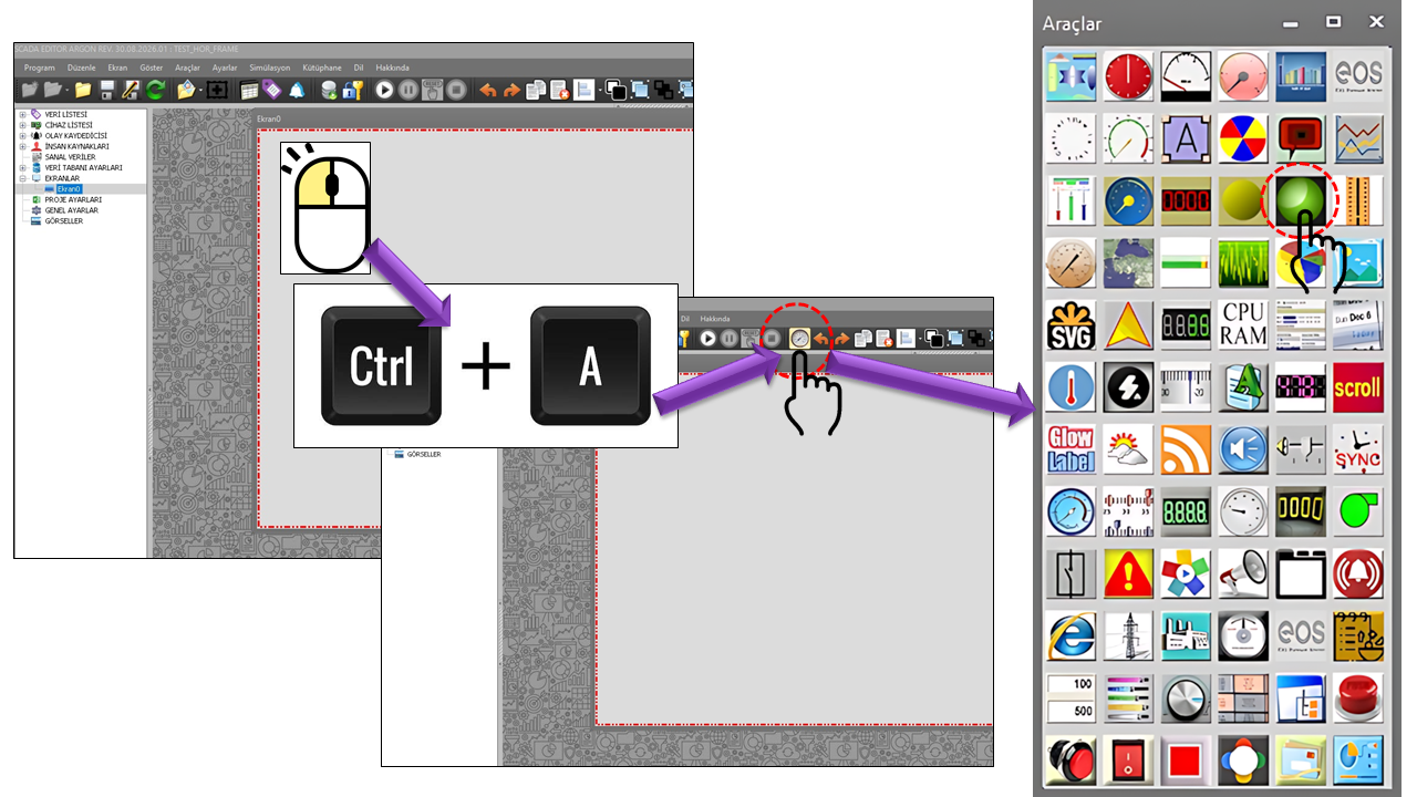
LEDBULB is used to convert a numerical process value into an LED behavior that can be understood at a glance, rather than displaying the entire numerical value to the operator. It indicates whether the value meets a specific condition or which operating range it falls within.
This approach is particularly valuable on large SCADA screens. Instead of reading the numerical value at every point, operators can quickly recognize important conditions through color, visibility, or blinking. Using colors to highlight live data and alarm conditions in HMI/SCADA design is also an approach emphasized in industrial HMI design guidelines.
Instead of displaying numerical data directly, it is converted into a meaningful visual state: data changes → state is determined → LED appearance changes.
Allows the operator to visually recognize the defined process state before reading the numerical value.
Separate LED colors can be defined for three different states
using State1Color, State2Color, and
State3Color.
Behaviors such as blinking and audible warnings make critical conditions more noticeable both visually and audibly.
For a constant-value alarm, the LED can be hidden when the data remains below a defined lower limit; it becomes visible again when the condition is no longer met.
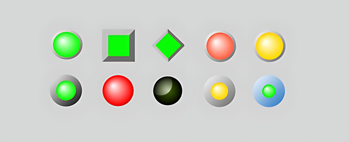
The LED shape used by LEDBULB is not limited to a single
appearance. The LED's basic geometry can be changed using the
LBSekil enumeration. This allows the same data logic to be
presented using different LED shapes suited to the screen's graphic design.
State1Color
State2Color
State3Color
| Technical Value | English Equivalent | Purpose |
|---|---|---|
Threedimention |
Three-Dimensional | Uses a three-dimensional visual appearance for the LED. |
Ellipse |
Ellipse | Provides a compact, classic LED/lamp appearance. |
Rectangle |
Rectangle | Can be used for status boxes or rectangular display areas. |
Diamond |
Diamond | Provides a distinctive status indicator, particularly in equipment symbols or directional graphics. |
LED shape, color, and alarm behavior can be considered independent design layers. This allows the same state logic to be used with different visual languages across different process screens.
One of LEDBULB's most important features is that its input data does not
have to be evaluated simply as "present/absent." Depending on the selected
AlarmType value, the data can be compared against thresholds
and converted into an LED state that is on/off, colored, or blinking.
In the supplied operating algorithm, the three-color mode
creates three data ranges using the Lower Limit and
Middle Limit: below the lower limit, between the lower
and middle limits, and at or above the middle limit. Although the
MaxValue property is included in the control's general
range definition, these are the limits directly used by the three-color
comparisons in the supplied operating code.
One of the strongest features of the LEDBULB control is that its operation is not limited to reading connected data and switching the LED on or off. Depending on the selected Alarm Type, the same data can be evaluated using different methods, allowing the LED's visibility, color, and blinking behavior to be changed.
This structure allows a single LED control to be used as a simple status indicator, a two-level color indicator, a three-level status indicator, or a blinking warning indicator for critical conditions. In addition, the Constant Value Alarm makes it possible to monitor not only the data level but also whether the value changes over a specified period.
Data is read → evaluated according to the selected Alarm Type → compared against thresholds → LED state is determined → color, blinking, and audible warnings are applied if necessary.
Normalwith2states is one of the most basic operating
methods of LEDBULB. In this method, the LED has two fundamental
states: the state in which the LED is off and the state in which
the LED is on.
The data connected to the control is compared with the Lower Limit. The LED remains off when the data is below the Lower Limit. When the data reaches or exceeds the Lower Limit, the LED turns on.
This method is particularly suitable for indicating whether a process condition has been met. For example, the LED can turn on when a measured value used to determine whether equipment is operating reaches a specified level.
When monitoring a pump's operating state through its current value, the LED can remain off while the current is below the defined Lower Limit. When the current exceeds this limit, the LED can illuminate to visually indicate that the pump is running.
Coloredwith2states enhances the two-state structure
with color information. The LED can remain visible
in both states while displaying different colors depending on the
range of the connected data.
When the data is below the Lower Limit, Color 1,
defined by State1Color, is used. When the data reaches
or exceeds the Lower Limit, Color 2, defined by
State2Color, is used.
This approach allows the LED to convey more information than simply being on or off. In addition to whether the LED is illuminated, the operator can identify its current state through color.
The colors used for Color 1 and Color 2 can be configured according to the application's meaning. LEDBULB can therefore be used for two-state visual indications such as low/sufficient, standby/running, or normal/warning.
Coloredwith3states is an operating method that
provides more detailed state indication with LEDBULB. Two
thresholds divide the data into three separate ranges, and a
different LED color can be defined for each range.
The first threshold is the Lower Limit, and the second is the Middle Limit. The data is therefore divided into three operating regions: low, intermediate, and high.
State1Color is used for the first range,
State2Color for the second range, and
State3Color for the third range. A single LED
thus becomes a visual indicator capable of distinguishing three
different process levels at a glance.
| Data Range | LED Color | Interpretation |
|---|---|---|
Data < Lower Limit |
State1Color |
First state |
Lower Limit ≤ Data < Middle Limit |
State2Color |
Second state |
Data ≥ Middle Limit |
State3Color |
Third state |
This structure can be used to provide a three-level status summary for process temperature, pressure, level, load, current, or similar analog values. For example, the second color can be displayed when a process value moves from the normal range into the warning range, and the third color when it reaches the critical range.
The first color can be used when the temperature is below the Lower Limit, the second color between the Lower and Middle Limits, and the third color at or above the Middle Limit. This allows the operator to quickly identify the temperature's operating range without having to read the numerical value.
Normalflashwith2states combines two-state LED logic
with a blinking behavior. When a critical or
specified condition occurs, the LED does not simply turn on; it
also blinks, drawing the operator's attention more effectively.
The LED remains off while the data is below the Lower Limit. When the data reaches or exceeds the Lower Limit, the LED becomes active and starts blinking.
Instead of remaining steadily illuminated, the LED generates a dynamic visual warning in this operating mode. As a result, conditions that require the operator's attention can be more easily distinguished among static indicators.
Coloredflashwith2states adds blinking to the
two-color state logic. The LED's state is therefore represented
through both color and movement.
When the data is below the Lower Limit, the LED is displayed
steadily using State1Color. When the data reaches
or exceeds the Lower Limit, the LED switches to
State2Color and starts blinking.
This structure is particularly useful when the second state represents not merely a different process level but a condition that requires additional operator attention.
Coloredflashwith3states is a more advanced form of
the three-state color logic. The data is displayed in three
different ranges using three different colors, and the
third state is additionally highlighted by
blinking.
When the data is below the Lower Limit, the first color is displayed steadily. Between the Lower Limit and the Middle Limit, the second color is displayed steadily. When the data reaches or exceeds the Middle Limit, the third color becomes active and the LED starts blinking.
This method gives the third level of a three-level process state greater visual priority. The operator can quickly recognize not only that the state has changed, but also that the highest defined state range has been reached.
For process pressure, the low range can be assigned the first color, the normal/warning range the second color, and the critical pressure range the third color. When the critical range is reached, blinking the LED in the third color makes the condition more noticeable than the other levels.
Unlike other alarm types, Constantdataalarm focuses
less on whether the data exceeds a particular threshold and more
on whether the data remains unchanged for a specified
period.
When the control reads new data, the value is compared with the previous reference value. If the data has changed, the new value becomes the reference and the constant-value timer is restarted. If the data remains unchanged, the elapsed time continues to be monitored.
If the data remains unchanged beyond the specified time limit, a constant-value alarm is triggered. In the source algorithm, the LED is then set to red, blinking is enabled, and an audible warning is generated if Use Sound Warning is enabled.
A conventional threshold alarm answers the question "Has the value exceeded a certain level?", whereas a constant-value alarm answers "Has the value remained unchanged for the expected period?".
If a sensor value that is normally expected to change continuously remains exactly the same for a long period, the sensor, communication link, or data-update mechanism may need to be investigated. LEDBULB's constant-value alarm can help make such conditions visually noticeable.
LEDBULB's alarm types are essentially different visual representations of the same data. When selecting a type, consider not only the LED color but also the kind of information that needs to be communicated to the operator.
| Operating Method | Number of States | Color | Blinking | Main Purpose |
|---|---|---|---|---|
Normalwith2states |
2 | Single appearance | No | Simple on/off state indication |
Coloredwith2states |
2 | 2 colors | No | Distinguishing two different states by color |
Coloredwith3states |
3 | 3 colors | No | Displaying a three-level process state |
Normalflashwith2states |
2 | Single appearance | Yes | Emphasizing a critical condition through movement |
Coloredflashwith2states |
2 | 2 colors | Yes | Emphasizing a state through color and movement |
Coloredflashwith3states |
3 | 3 colors | In the third state | Highlighting the critical level within a three-level state |
Constantdataalarm |
Time-dependent | Depends on alarm state | During alarm | Monitoring whether data remains unchanged for a specified period |
In LEDBULB, Alarm Type is more than just an alarm option; it is the fundamental operating method that determines how connected data is communicated visually to the operator.
In the source code, these behaviors are evaluated using the data read during the control's update cycle. In three-color and blinking modes, threshold comparisons directly determine the LED color and blinking state.
Constantdataalarm is a special alarm method that operates differently from LEDBULB's conventional threshold alarm. It monitors not only the value of the data but also whether the value changes over a specified period.
In the supplied algorithm, the newly read value is first compared with
the reference value. When the value changes, the reference time is
updated. If the value remains unchanged, the elapsed time is calculated.
When this time exceeds the limit defined by
ConstantValueTimeLimit, the LED turns red, blinking is
enabled, and an audible warning is generated if sound notification is enabled.
If a motor's current, speed, or pressure value is normally expected to change continuously but remains unchanged for the specified period, the data may not be updating. In this case, LEDBULB can help visually monitor not only the question "Is the value high?" but also "Is the value still changing?"
ConstantValueHideLED is one of the notable features of the
constant-value alarm. In the source algorithm, when
Use Constant Data Limit is enabled and the data is
below the Lower Limit, the LED is kept dark gray and
blinking is disabled. When the data no longer meets this condition,
the constant-data duration is evaluated again.
It can be used to prevent unnecessary visual clutter when values are low or considered insignificant to the process. This allows the LED to enter the operator's field of attention only when it reaches a meaningful operating range or an alarm condition occurs.
Hiding the LED does not automatically mean "no data" or "device fault." The meaning of an invisible LED must be clearly defined for the operator as part of the design.
When UseSoundWarning is enabled, audible warnings can be
generated under selected critical conditions. In the source algorithm,
when a threshold condition occurs, SESKULLAN is checked
and the audible-warning call is made.
Sound provides an additional channel alongside the LED's visual state. This approach can be especially useful when the operator cannot continuously look at the same area. Industrial HMI examples also show alarm conditions being reinforced with audible warnings in combination with color and blinking.
Audible warnings should be reserved for conditions that genuinely require operator attention rather than being used as general notifications for every data change. Otherwise, screens that produce continuous sounds can lead to alarm fatigue. Consistent meanings for colors and sounds across the facility are also important.
LEDBULB's compact, easily readable design is particularly useful on SCADA screens where many process values must be summarized on a single screen. The following examples illustrate how the control can be used with different alarm and state methods.
Turn on the LED when motor current or operating feedback exceeds a specified threshold; make it blink under critical conditions.
Summarize low, normal, and high temperature ranges using three different LED colors.
Use one color below the lower limit, a second color in the normal range, and a third color at high levels.
Detect when a sensor or process value remains unchanged for the specified period using the constant-value alarm.
Compactly summarize the states of pumps, fans, compressors, valves, and similar equipment using small LEDs.
Highlight the critical level using blinking in the third state color and an optional audible warning.
The following table summarizes the LEDBULB properties in the supplied source code, together with their equivalents in the EOS terminology dictionary.
| Property | EOS English Equivalent | Default | Description |
|---|---|---|---|
UCType |
Control Type | LEDBULB |
Defines the User Control type within EOS SCADA. |
UpdateInterval |
Update Interval | 1000 ms |
Defines the control's data update interval. |
DecimalPoint |
Decimal Places | 0 |
Defines the decimal display setting used when evaluating numerical values. |
UCBackColor |
Control Background Color | Transparent |
Defines the control's overall background color. |
UCForeColor |
Control Foreground Color | Black |
Defines the control's primary foreground/text color. |
UCFont |
Control Font | Arial Narrow, 8.25 pt, Bold |
Defines the control's primary font settings. |
LEDType |
LED Type | Ellipse |
Defines the geometric shape of the LED. |
AlarmType |
Alarm Type | Normalwith2states |
Defines the state/alarm method used to convert data into LED behavior. |
MinValue |
Minimum Value | 50 |
Defines the configured lower value limit for the control. |
MedValue |
Middle Value | 75 |
Defines the value that can be used as the middle threshold in three-state color evaluation. |
MaxValue |
Maximum Value | 100 |
Defines the configured upper value limit for the control. |
State1Color |
State 1 Color | Lime |
Defines the color used for the first LED state. |
State2Color |
State 2 Color | Yellow |
Defines the color used for the second LED state. |
State3Color |
State 3 Color | Red |
Defines the color used for the third LED state. |
BorderColor |
Border Color | Gray |
Defines the color of the LED border. |
BorderWidth |
Border Width | 4 |
Defines the width of the LED border. |
UseSoundWarning |
Use Sound Warning | false |
Determines whether audible warnings are used for defined critical conditions. |
UseConstantValueAlarm |
Use Constant Value Alarm | false |
Determines whether constant-data alarm behavior is enabled. |
ConstantValueTimeLimit |
Constant Value Time Limit | 660000 ms |
Defines the time limit after which an alarm occurs if the value remains unchanged. |
ConstantValueHideLED |
Hide LED for Constant Value | false |
Enables hiding the LED under the specified lower-limit condition during constant-value alarm operation. |
Since LEDBULB is a small control, it is a powerful tool for summarizing many pieces of equipment or status information on a single screen. However, the meanings of colors and blinking behaviors must remain consistent throughout the screen.
This approach is consistent with HMI design principles that recommend using colors to highlight live data and alarm information. Rockwell's PlantPAx graphics approach also recommends reserving colors primarily for emphasizing live data and alarms.
The meanings of colors such as red, yellow, and green should be standardized across the facility. For critical conditions, meaning should be reinforced where possible through blinking, sound, or supplementary text/icons. This prevents the operator interface from relying exclusively on color distinctions.
LEDBULB (SIMPLE LED LAMP) is a powerful status communication tool for SCADA screens despite its small size. Its ability to convert connected data into on/off, colored, blinking, or constant-value alarm behavior makes it a more comprehensive user control than a simple LED graphic.
Three separate state colors, different LED shapes, audible warnings, blinking under critical conditions, and the ability to hide the LED under specified constant-value conditions allow the same control to serve different purposes, including equipment status, process levels, alarm summaries, data-update monitoring, and critical operating conditions.
LEDBULB = a compact SCADA indicator that converts data values into visual states that operators can recognize quickly.

Free Software Download Center
Software for industrial data collection, monitoring, and analysis.

Technical Support
Software documentation, sample code, and practical technical information.
You can contact us regarding EOS software, technical documentation, or industrial data communication.