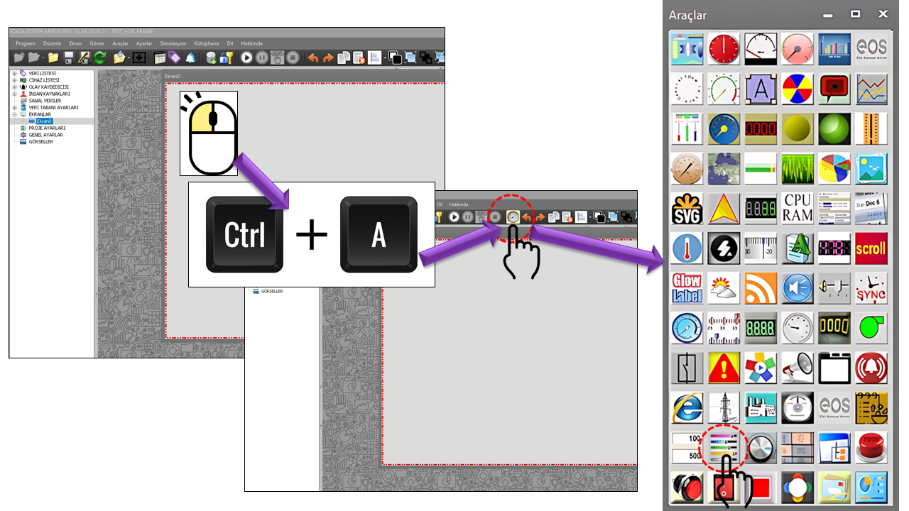
What Is SLIDER?

SLIDER is a user control that allows a process value to be visually selected within a defined minimum and maximum range on a SCADA screen and writes the selected value to the controller. This distinguishes it from conventional linear indicators: while a linear indicator is generally intended for monitoring, SLIDER uses the same visual approach for operator input.


The slider can be adapted to different process screens through properties such as its position, value range, thumb shape, ticks, text ticks, border, and rotation. The SLSliderTur options in the source code indicate that the control can be used in four different visual and functional types.

Caution — data is written to the controller: SLIDER is a write control. A selection made by the operator on the slider may change the connected controller variable or setpoint. Therefore, authorization levels, the minimum and maximum range, and the safe operating limits of the process must be considered together. Limits on the HMI/SCADA side must not replace independent limits and interlock mechanisms on the controller side.

SLIDER Types — Four Different Appearances

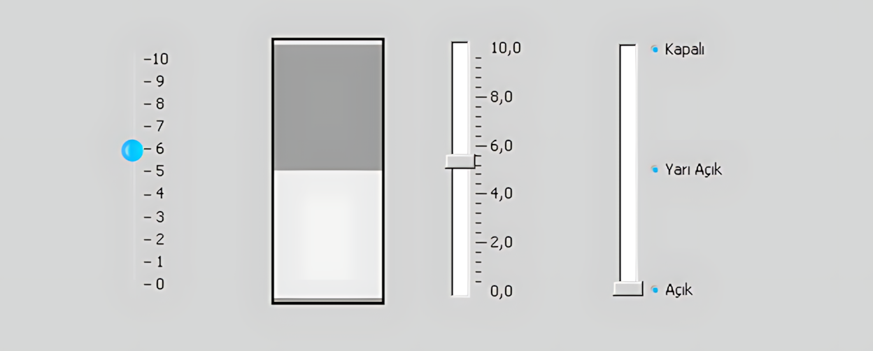
The four control types shown in the illustration are presented in the same order as the SLSliderTur options in the source code. Each type provides a different way for the operator to select a value and a different visual presentation on the screen.

01

Mac Trackbar

−10
−5
0
5
10

Mactrackbar is the first SLIDER type in the source code. It uses a classic trackbar-style appearance and presents value selection on a compact linear scale.

Use: Screens where operators need to select a specific analog value quickly, screen space is limited, or a classic trackbar appearance is preferred.

02

3-Position Rocker Switch

HIGH MEDIUM LOW

Switchrocker3way has a switching mechanism similar to a wall-mounted light switch used in homes. However, instead of two positions, this control offers three distinct positions: upper, middle, and lower. Each position can represent a different selection or a different value to be written to the controller.

Use: Three-stage speed selection, pump or fan operating levels, capacity selection, operating modes, and applications where the operator needs to choose between three different commands or values.

03

Slider

100 80 60 40 20 0

Slider is a linear control type that allows continuous value selection within a defined minimum and maximum value range. In terms of operating principle, it is similar to the Mactrackbar control: the operator moves the thumb along the linear scale to select the desired value, which is then written to the controller. The main difference between Slider and Mactrackbar lies not so much in their operating principle as in their visual design and how the value is presented to the user.

Scale: The slider can include a scale and ticks indicating the value range. The thumb is not limited to just a few predefined points; it can be moved within the defined minimum and maximum range to select intermediate values as well.

Relationship with Mactrackbar: Slider and Mactrackbar use similar linear sliding mechanisms for value selection. Slider implements this approach with a different visual design and scale presentation. The two controls can therefore be considered different visual representations of the same type of continuous value selection.

Use: Operator adjustment of continuous variables such as speed, flow rate, pressure, temperature setpoint, valve position, analog output, and motor speed.

04

Selection Slider

Off Low Medium High On

Switchslider is a control type that uses a linear slider appearance and allows the user to select among the VALUE_POINT_COLLECTION values defined by the user. The slider thumb moves between the defined selection points and writes the selected point's value to the controller.

VALUE_POINT_COLLECTION: Each selection point has ItemValue and ItemText properties. For example, a point can be defined with ItemValue = 50 and ItemText = "Medium". When the operator moves the slider to that point, the value 50 is selected, and the text Medium is displayed to describe the selection.

Use: Control screens requiring selection among predefined operating stages, speed levels, pump or fan stages, operating modes, valve positions, or specific values.

How Writing to the Controller Works

The key difference behind SLIDER's indicator-like linear appearance is that operator interaction is treated as an input. When the operator moves the thumb or selects a position according to the control type, the control produces a value within the defined range. This value can then be used as a process or setpoint value to be written to the controller.

01The operator selects the slider.
→
02The position corresponds to a value within the MinValue–MaxValue range.
→
03Authorization limits are validated.
→
04The selected value is used for the write operation.

Why Is Authorization Important?

AuthorizationLevel is not merely a visual setting for SLIDER. Because data can be written to the controller, defining which users can make changes and at what level is operationally important.

ACCESS

Monitoring

Can be used as a basic level in scenarios where viewing a screen containing the control must be separated from write privileges.

ACCESS

Operation

Can be used in applications where operators need to change specific setpoints as part of process operation.

ACCESS

Engineering

Can be used when commissioning, configuration, and engineering changes must be separated from operational users.

ACCESS

Superuser

Can be considered for administrative or specialized maintenance scenarios requiring the highest access level.

Important: Adding an SLIDER that writes to the controller to an operator screen is not recommended until the authorization level has been correctly defined. For process parameters such as motor speed, valve position, temperature setpoint, pressure setpoint, and similar values, HMI/SCADA authorization must be considered together with the limit and interlock logic on the controller side.

MinValue and MaxValue — The Basis of the Value Range

MinValue and MaxValue are the two fundamental limits of the value range presented to the user by SLIDER. Regardless of the slider type, the operator's selection range must be clear and appropriate for the process purpose.

Property Default Role Example Use
MinValue 0 Lower value limit Starting values such as 0% minimum speed, 0 bar, or 0 Hz
MaxValue 10 Upper value limit A range of 10 units or the maximum setpoint permitted by the process
DecimalPoint 0 Decimal-place setting for numeric display Readable display of fractional setpoints

Note: This range defines the selection limits in the control's user interface. Safety-critical limits must also be validated independently in the controller/PLC logic.

Tracker, Ticks, and Markers

It is important not only that SLIDER operates correctly, but also that the operator can quickly and accurately interpret the selected value. For this reason, the tracker, ticks, text ticks, and marker groups can be configured separately in the source code.

Tracker

TrackerColor, TrackerSize, and TrackerShape determine the appearance of the slider's moving component.

Tick Structure

TickStyle, TickColor, TickFrequency, and TickHeight control the appearance of marks along the scale.

Tick Items

The TickItems collection allows custom text to be defined for specific value points. Each item contains ItemValue and ItemText information.

Markers

MarkersStyle, MarkersBevelStyle, MarkersColor, and MarkersSize determine the shape and appearance of the markers.

Orientation, Rotation, and Border

SLIDER is not limited to a single horizontal appearance. The control can be oriented at 0, 90, 180, or 270 degrees using RotationAngle. This feature can be used to create vertical setpoint controls or indicators rotated to suit the screen layout.

Property Default Description
RotationAngle 0 Degrees Determines the orientation of SLIDER.
BorderColor Black Determines the border color.
BorderStyle None Determines the type of border appearance.
TrackLineColor Silver Determines the color of the slider track line.

General Properties

Property EOS English Equivalent Default Description
UCType Control Type SLIDER Defines the type of user control.
UpdateInterval Update Interval 1000 ms Determines the control's update interval.
DecimalPoint Decimal Places 0 Determines the decimal precision used to display numeric values.
UCBackColor Control Background Color Silver Determines the control's background color.
UCForeColor Control Text Color Black Determines the control's primary text color.
UCFont Control Font Tahoma, 8 pt Determines the control's font.

SLIDER and Range Settings

Property EOS English Equivalent Default Description
SliderType Slider Type Mactrackbar Determines which of the four SLIDER types the control uses.
TrackLineColor Track Line Color Silver Determines the color of the sliding/track line.
RotationAngle Rotation Angle 0 Degrees Determines the orientation of the control.
MinValue Minimum Value 0 Determines the lowest selectable value.
MaxValue Maximum Value 10 Determines the highest selectable value.
TrackerColor Tracker Color DeepSkyBlue Determines the color of the moving tracker.
TrackerSize Tracker Size 16 × 8 Determines the tracker's width and height.
TrackerShape Tracker Shape Ellipse Determines the geometric shape of the tracker.

Tick and Text Tick Settings

Property EOS English Equivalent Default Description
TickStyle Tick Style Bottomright Determines the position of ticks on the control.
TickColor Tick Color Black Determines the color of the tick marks.
TickFrequency Tick Frequency 1 Determines the frequency of ticks along the range.
TickHeight Tick Height 4 Determines the height of the tick marks.
TickItems Tick Items VALUE_POINT_COLLECTION[] A collection of custom value/text points.
TextTickStyle Text Tick Style Bottomright Determines the position of tick labels.
TextTickColor Text Tick Color Black Determines the color of tick labels.

VALUE_POINT_COLLECTION: Each item defines a numeric position through ItemValue and the displayed text through ItemText. It can be used to associate a specific value with a meaningful label such as “On,” “Off,” “Low,” “Medium,” or “High.”

Marker Settings

Property EOS English Equivalent Default Description
MarkersStyle Marker Style Circle Determines the shape of the marker.
MarkersBevelStyle Marker Bevel Style Sunken Determines whether the marker appears recessed or raised.
MarkersColor Marker Color DeepSkyBlue Determines the marker's color.
MarkersSize Marker Size 4 Determines the marker's size.

Option Sets — SLIDER Types

SLSliderTur

Technical Value Description
Mactrackbar Mac Trackbar
Switchrocker3way 3-Position Rocker Switch
Slider Slider
Switchslider Selection Slider

SLKenarSekli

Technical Value Description
None None
Dashed Dashed
Dotted Dotted
Inset Inset
Outset Outset
Solid Solid
Adjust Adjust
Bump Bump
Etched Etched
Flat Flat
Raised Raised
Raisedinner Raised Inner
Raisedouter Raised Outer
Sunken Sunken
Roundedsides Rounded Sides
Sunkeninner Sunken Inner
Sunkenouter Sunken Outer

GNAciBilgisi

Technical Value Description
Zerodegrees 0 Degrees
Ninthydegrees 90 Degrees
HundredEightydegrees 180 Degrees
Twohundredseventhydegrees 270 Degrees

SLIgneTuru

Technical Value Description
Ellipse Ellipse
Rectangle Rectangle
Bar Line
Barindicator Bar Indicator
Barindicatorlight Illuminated Bar Indicator
Pointer Pointer

MCKonum

Technical Value Description
None None
Topleft Top Left
Bottomright Bottom Right
Both Both

SLLedTuru

Technical Value Description
Circle Circle
Square Square
Line Line
None None

SLGorunum

Technical Value Description
Sunken Sunken
Raised Raised
None None

GNYetkiSeviyesi

Technical Value Description
None No Authorization
Monitor Monitoring
Operation Operation
Engineering Engineering
Superuser Superuser

SCADA Use Cases

Motor Speed Setpoint

Selecting a motor speed reference within a range of 0–100% or another range expressed in engineering units. A continuous slider type can be used for quick operator adjustments.

Valve Opening

Operator adjustment of valve opening from 0–100%. The value range and position limits on the controller side must be considered together.

Three-Stage Operation

Selecting three predefined operating levels such as Low / Medium / High. The Switchrocker3way type is visually suitable for this use.

Process Setpoint

Quickly adjusting an analog setpoint such as temperature, pressure, or flow rate. If precise numeric entry is required, the control can be designed to work alongside a numeric input control.


Technical and Usage Notes

  • SLIDER should not be designed as a display-only control: its key distinction is that it supports operator input and write operations.
  • MinValue / MaxValue must not be confused with the actual safety limits of the process.
  • AuthorizationLevel must be defined according to the intended use.
  • Independent limit, interlock, and safe-state checks must be implemented on the controller side.
  • For processes requiring very frequent, continuous writes, the effect of write behavior on communications and controller load must also be evaluated.
  • Vertical or horizontal layouts can be designed using RotationAngle; however, the orientation must be presented clearly so that the operator can interpret the value correctly.
  • Since the source code does not contain a specific property demonstrating data binding, no tag-binding mechanism has been assumed here.

Summary

SLIDER is a user control designed to let operators select analog or stepped process values using a visual slider and write the selected value to the controller. It has four types: Mactrackbar, Switchrocker3way, Slider, and Switchslider. Its appearance can be configured in detail using tracker, tick, marker, border, and rotation settings.

Because it can write values to the controller, SLIDER must be designed with not only its visual appearance in mind, but also authorization, the value range, and the safety and limit logic on the controller side.