
Free Software Download Center
Software for industrial data collection, monitoring, and analysis.
BARASET • XML • MODBUS HOLDING REGISTER • EÜAŞ DATA INTEGRATION
MAESTRO Recorder Emulator EÜAŞ (MAESTROrecsim.exe) is a specialized recorder emulator developed to meet the requirements of the Electricity Generation Corporation of Türkiye (EÜAŞ). It reads BARASET values that are centrally updated in XML format and published by TEİAŞ for power plants, and publishes these values as MODBUS Holding Registers, as if they were being received from a MODBUS-enabled recorder device.
This allows BARASET values that are not physically measured or directly available in existing systems, but need to be incorporated into data systems, to be transferred to SCADA and other data acquisition systems via the MODBUS protocol. The same architecture can also be used to retrieve data other than BARASET from a central source in XML format and in a format supported by the software, and incorporate that data into the system.
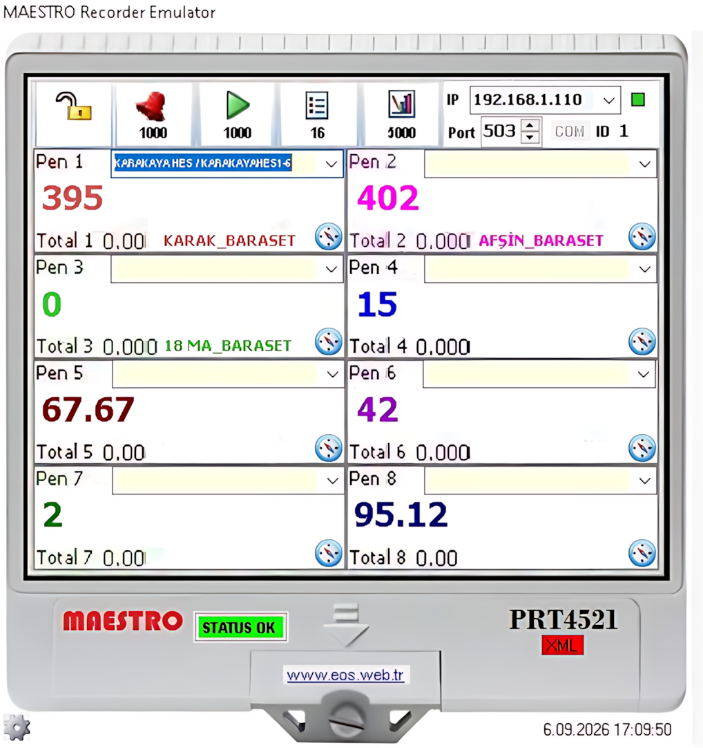
In power generation facilities, some data may not be directly available from the plant's measurement systems. However, such data may need to be obtained from a central system and incorporated into the plant's data systems. BARASET is an important example of this type of integration requirement.
MAESTRO Recorder Emulator EÜAŞ reads data centrally updated in XML format and converts it into a MODBUS Holding Register structure that can be readily used by plant-side systems. This creates a software bridge between centrally provided data and the plant's data acquisition / SCADA system.
Basic data flow: TEİAŞ / Central XML Data → MAESTRO Recorder Emulator EÜAŞ → MODBUS Holding Register → EÜAŞ SCADA / Data System
The primary function of the program is to receive XML data updated at a central location and make this data readable via MODBUS. This allows the existing MODBUS data acquisition infrastructure to be used without requiring the upper-level system to process the XML file directly.
Integration approach:
This architecture is not limited to BARASET. Other data published centrally in XML format and conforming to a data format supported by the program can also be transferred to plant systems using the same approach.
When the program is started, a total of 8 channels are displayed in the user interface. Each channel operates like a recorder channel. Values can be entered directly into the channels manually, and the plant can also be selected from the interface for the data to be received centrally for the relevant channel.
When a plant is selected for a channel, the BARASET values read from
the central system for that plant can be transferred to the data
program of the relevant channel. This allows hourly plant-specific
values to be supplied to the system via MODBUS.
MODBUS channel addresses:
These addresses represent the starting addresses of the MODBUS Holding Registers for the corresponding channels.
The clock icon next to each channel opens the 24-hour data entry area for that channel. Hourly values for both Today and Tomorrow can be viewed and entered manually in this area.
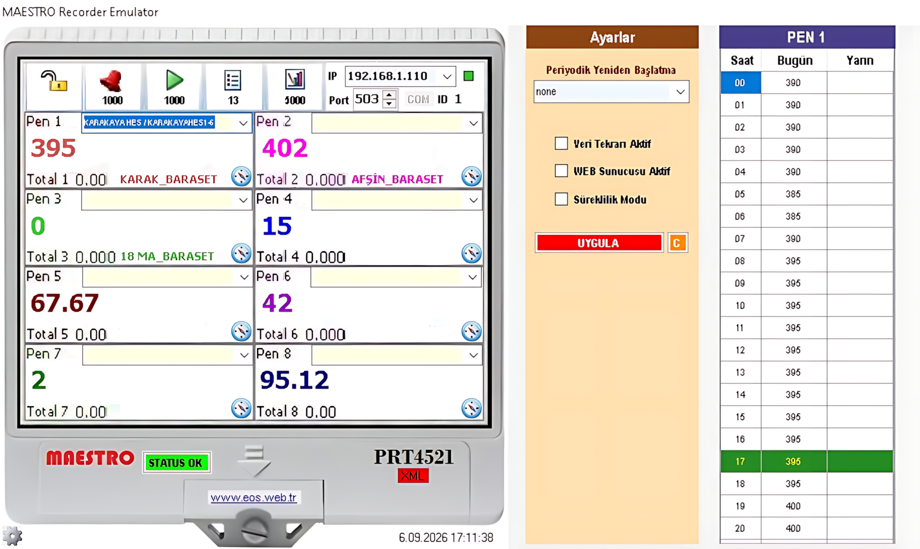 BARASET values received from the central system can also be used in
the hourly data structure of the relevant channel. When necessary,
the user can manually modify the values or enter data directly.
A value entered or received from the central system for a specific
hour begins to be published at the channel's
MODBUS Holding Register address when that hour is reached.
BARASET values received from the central system can also be used in
the hourly data structure of the relevant channel. When necessary,
the user can manually modify the values or enter data directly.
A value entered or received from the central system for a specific
hour begins to be published at the channel's
MODBUS Holding Register address when that hour is reached.
Single-channel time table: Before opening the 24-hour data table of another channel, the currently open channel's table must be closed by clicking the clock button of that channel.
After the program is started, the IP address and port number to be used for MODBUS output are selected. The output is then started by clicking the STATUS OK button.
Indications that the output has started successfully:
These indicators show that the MODBUS output service has been started successfully.
When the WEB Server Active option in the program's Settings window is enabled, the published data and data read addresses can be viewed as a live table through the web server.
The live table is updated every 15 seconds. The address used by the WEB server is generated using the IP address selected for MODBUS output.
The WEB Server feature can be used to quickly monitor channel values and the corresponding MODBUS read addresses during commissioning, testing, and maintenance activities.
| Setting | Function |
|---|---|
| Continuous Mode Active | Keeps the program running continuously. Even if the program is closed, it automatically restarts itself. |
| Data Repetition Active | At the change of day, copies the previous day's 24-hour data to the Tomorrow column. |
These options are particularly useful in plant applications that need to provide continuous data service and in situations where the same daily data profile is repeatedly used.
After all operations have been completed, the program can be minimized by pressing the ESC key while the program window is active or by double-clicking the program window.
The program does not completely close; it continues running as a small icon in the Windows notification area (system tray). Double-clicking this icon restores the main program window.
This feature can be used to prevent the program from remaining permanently visible as an open desktop window while MODBUS data output continues.
Other program settings are stored in the MAESTROrecsim.dat input file. The required parameters can be edited manually using NOTEPAD or a similar text editor.
Important: When making changes to the configuration file, the parameter structure expected by the program must be preserved. An incorrect or invalid setting may prevent the program from operating as expected.
The program must be run as Administrator to operate correctly. The required administrator permissions and relevant application settings should be configured in advance on Windows.
MAESTRO Recorder Emulator EÜAŞ was developed to integrate BARASET and similar data received centrally in XML format into EÜAŞ data systems via the MODBUS protocol.
Execution requirement: The program must be run as Administrator to operate correctly. Other program settings can be configured through the MAESTROrecsim.dat file.
Related files:
Free Software Download Center
Software for industrial data collection, monitoring, and analysis.

Technical Support
Software documentation, sample code, and practical technical information.
You can contact us regarding EOS software, technical documentation, or industrial data communication.