
Free Software Download Center
Software for industrial data collection, monitoring, and analysis.
MULTIPLE MODBUS SOURCES • 192 DATA POINTS • SINGLE MODBUS TCP SERVER • LIVE WEB MONITORING
MAESTROrecsim MULTIMODBUS Gateway is a MODBUS Gateway software designed to make data collected from multiple MODBUS sources available to higher-level systems through a single MODBUS server interface. Data received from different devices and sources can be consolidated at a single point and made accessible to SCADA, HMI, and data acquisition applications.
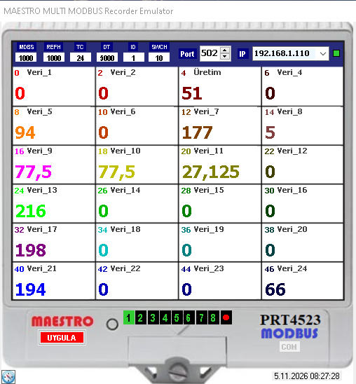
The software supports up to 192 data points. These data points can be monitored live on the main screen, organized into eight separate pages with 24 data points each. This makes it possible to monitor data from numerous MODBUS devices centrally and transfer it to higher-level systems through a single MODBUS publishing address.
In industrial facilities, measuring instruments, power analyzers, meters, PLCs, recorders, and other automation equipment often operate as separate MODBUS sources. Requiring the higher-level system to communicate with each device individually can complicate connectivity, addressing, and data management.
MAESTROrecsim MULTIMODBUS Gateway reads selected data from configured MODBUS sources and consolidates them under a single MODBUS publishing endpoint. Instead of connecting to numerous devices individually, the higher-level system can read data from the common data area published by the gateway.
Basic approach: Multiple MODBUS devices / sources → MAESTROrecsim MULTIMODBUS Gateway → Single MODBUS publishing endpoint → SCADA / HMI / Data Acquisition System
The gateway uses the MODBUS addresses and reading definitions of the source devices while organizing the data presented to the higher-level system at a single access point. The source device addresses and the gateway publishing addresses are two separate configuration layers. This distinction should be taken into account during commissioning.
The software supports up to 192 data points. The main monitoring screen displays 24 data points simultaneously in real time. By clicking the page selection buttons numbered 1–8 at the bottom of the screen, the corresponding group of 24 data points can be displayed.
Page and data capacity:
Each page displays only its corresponding group of 24 data points. The displayed values are updated in real time as they are read from the sources.
The red dot button at the bottom starts automatic page switching. Once activated, the screen cycles sequentially through all eight pages, displaying the live list of 24 data points on each page. This feature allows operators to monitor all 192 data points sequentially without manually changing pages.
To operate the gateway, the endpoint devices/sources from which data will be read must first be configured, followed by the data points to be collected from these sources. Each data point is assigned a descriptive name, an appropriate reading mode, and a value token specifying its source and address. The data name serves as a descriptive label for monitoring on the main screen and identifying the data in the higher-level system.
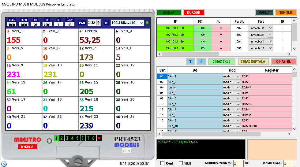
The fields used to define source devices should be configured according to the communication and addressing characteristics of each device:
| Field | Description | Check / Note |
|---|---|---|
| Device IP Address | The IP address of the MODBUS device accessed over TCP/IP. | Verify IP connectivity, subnet settings, and network routing. |
| Communication Port | The TCP port on which the remote device accepts MODBUS TCP connections. | Use the port specified in the manufacturer's documentation and device configuration; do not assume port 502 for source devices. |
| Device Type | The type or format selection that affects how the data is interpreted. | Match the data type and byte order with the device documentation. |
| Device ID | MODBUS device address / unit identifier. | Verify the correct address, especially when using TCP-to-RTU converters or gateways serving multiple devices. |
| Timeout | The time allowed for a response from the source device. | Consider actual communication delays and device response behavior. |
| Frequency | The data reading frequency or polling interval. | Consider device capacity, response time, and network load. |
| Token | The definition of the register or digital status to be read. | Verify the register address and token syntax against the device documentation. |
After the endpoint devices have been configured, a name, mode, and value token are defined for each data point. The value token specifies the source and the address or rule used to read the data. The selected mode must be compatible with the register area and data length of the source.
| Mode | Meaning | Note |
|---|---|---|
mod-h |
32-bit value over MODBUS TCP; Holding Register. | For values using two registers, verify the data format and register order. |
mod-i |
32-bit value over MODBUS TCP; Input Register. | Read-only Input Register area. |
mod-r |
32-bit value over serial port MODBUS RTU. | Specified in the provided mode description as part of LOGGER PREMIUM. |
mod-hs |
16-bit value over MODBUS TCP; Holding Register. | Values using a single register. |
mod-is |
16-bit value over MODBUS TCP; Input Register. | Read-only values using a single register. |
mod-rs |
16-bit value over serial port MODBUS RTU. | Specified in the provided mode description as part of LOGGER PREMIUM. |
Data Format and Addressing: The way MODBUS register addresses are represented may vary depending on the manufacturer's documentation. The 16/32-bit data length, signed/unsigned interpretation, and byte/word order must be verified against the source device documentation. The availability of serial port MODBUS RTU modes in this gateway version must be separately confirmed against the technical scope of the relevant version.
The publishing IP address and publishing port used to provide the consolidated data are selected in the upper section of the program. This address and port define the MODBUS server endpoint that the higher-level system will use to connect to the gateway.
Default MODBUS TCP publishing port: 502
When selecting a port, check the computer's network interface, firewall rules, and any other services that may be using the same port. The higher-level system should be configured to connect using the publishing IP address and port number selected for the gateway.
Data read by the gateway from its sources is made available to the higher-level system through the configured publishing data area. Source-side MODBUS device addresses must not be confused with the MODBUS addresses presented by the gateway to the higher-level system. SCADA reading definitions must be configured according to the gateway's publishing address map.
To modify source device or data definitions, first click the STOP button in the upper section of the program to stop operation and enter configuration mode. After completing the required changes, click the START button. Finally, click the APPLY button on the main screen on the left to apply the changes.
Important: Follow the STOP / START / APPLY sequence when making configuration changes. To ensure that the new definitions are correctly reflected in the higher-level system, both source device communication and gateway publishing addresses must be checked.
Clicking the CLOCK button in the lower-left corner of the main screen opens a configuration window on the right side of the program. In this window, different MODBUS addresses and the data to be read from these addresses can be defined. Each data point can be assigned a meaningful name, allowing descriptive data names to be used on the monitoring screen instead of raw addresses.
When naming data points, descriptive names that identify the measured quantity and, where possible, its engineering unit should be preferred. For example, naming values read from a power analyzer as active power or values read from a meter as total energy makes operation and fault monitoring easier.
When the WEB option in the program is checked, the integrated WEB Server can be activated. This allows the data published by the gateway and their MODBUS addresses to be displayed live in a table through a web browser.
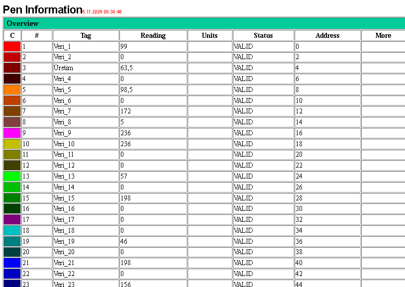
During commissioning and operation, the WEB table helps users view data names, current values, and their corresponding MODBUS addresses together. This screen can be used to visually verify the gateway's data publishing; it is not a protocol that replaces the higher-level system's MODBUS connection.
When the CONT option is checked, the program is configured to automatically restart itself if it is closed. This option can be used in installations where the gateway application is expected to run continuously on the operating computer.
Operational Note: The CONT option does not by itself resolve situations such as computer or operating system shutdown, power failure, or network disconnection. In applications requiring continuous operation, the availability of the computer, network, and source devices must also be ensured separately.
The application window can be minimized by double-clicking the program window. The program does not close completely; it continues running as a small icon in the Windows system tray.
To reopen the main screen, simply click the MAESTROrecsim MULTIMODBUS Gateway icon in the system tray. This feature allows the application window to be removed from the desktop while the MODBUS gateway service continues running.
Gateway architecture can be useful in various industrial applications where data from multiple MODBUS sources needs to be consolidated at a single point. The following examples illustrate scenarios in which the software's multi-source data acquisition and single MODBUS endpoint publishing approach can be used:
| Application | Potential Use |
|---|---|
| Energy Monitoring Systems | Consolidating measurements from power analyzers and electricity meters in different panels at a single MODBUS access point. |
| Water and Wastewater Facilities | Transferring data from pumping stations, flow meters, level transmitters, and other MODBUS devices to a centralized SCADA system. |
| Production Lines | Combining selected values read from different machines, PLCs, and process devices into a single higher-level system connection. |
| HVAC and Building Automation | Presenting data from chillers, boilers, air handling units, meters, and field controllers through a common MODBUS server endpoint. |
| Power Generation Facilities | Transferring MODBUS data from auxiliary systems, measuring instruments, and different equipment to a centralized monitoring layer. |
| Expansion of Existing SCADA Systems | Using the gateway as a single MODBUS server on the SCADA side instead of defining separate connections for numerous source devices. |
| Testing and Commissioning | Monitoring data from multiple MODBUS devices at a centralized point and verifying the higher-level system connection. |
Important Architectural Note: Using a gateway does not eliminate the communication capacity limitations of source devices. Polling intervals, timeout values, device response times, and network bandwidth must be evaluated together. Querying a large number of devices simultaneously and too frequently may create additional load on the source devices or the network.
MAESTROrecsim MULTIMODBUS Gateway is designed to transfer data read from multiple MODBUS TCP sources to higher-level systems through a single MODBUS TCP server. It consolidates data from different devices and control systems at a single MODBUS access point.
Operating Requirements: The necessary network access permissions must be provided for the program to operate correctly. The IP address and port used for MODBUS TCP publishing can be configured through the program. The default publishing port is 502.
Related Files:
Free Software Download Center
Software for industrial data collection, monitoring, and analysis.

Technical Support
Software documentation, sample code, and practical technical information.
You can contact us regarding EOS software, technical documentation, or industrial data communication.