
Free Software Download Center
Software for industrial data collection, monitoring, and analysis.
OPC DA SERVER • 192 DATA POINTS • 32-BIT MODBUS HOLDING REGISTERS • OPC DA → MODBUS TCP GATEWAY
MAESTROrecsim OPC DA is an OPC DA – MODBUS TCP Gateway software designed to read process data from OPC DA servers and make this data available to higher-level systems through a single MODBUS TCP server. Tag values accessible through the OPC DA interface are consolidated into a data area that can be read by SCADA, HMI, PLC, and data acquisition applications using MODBUS TCP.
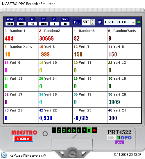
The program supports up to 192 data points. These data points can be monitored live on the main screen, organized into eight separate pages with 24 data points each. Each data point is published as a 4-byte (32-bit) value using two MODBUS Holding Registers.
In industrial automation systems, PLCs, DCS systems, process control software, energy management applications, and automation platforms from different manufacturers can expose their real-time data to other software applications through OPC DA servers. However, some SCADA, HMI, data logging, or data acquisition systems may not operate directly as OPC DA clients; they may support only a different communication interface, such as MODBUS TCP.
MAESTROrecsim OPC DA connects to an OPC DA server as a client, browses the tag structure defined on the server, retrieves the values of tags selected by the user, and publishes them in the MODBUS TCP Holding Register area. This allows process data accessible through OPC DA to be read by an upper-level system operating as a MODBUS TCP client.
Basic concept: OPC DA Server / Tags → MAESTROrecsim OPC DA → MODBUS TCP Holding Register → SCADA / HMI / PLC / Data Acquisition System
This architecture makes selected data available through a MODBUS TCP interface without modifying the existing OPC DA infrastructure or adding a new communication driver to the source application. The gateway treats tag selection on the OPC DA side and register mapping on the MODBUS side as two separate configuration layers.
A total of 192 data points can be configured in the program. The main monitoring screen displays 24 data points simultaneously in real time. The corresponding group of 24 data points can be selected by clicking the page numbers 1–8 at the bottom of the screen.
Page and data capacity:
Each page displays the 24 data points belonging to its corresponding group. Values read from the OPC DA server are updated on the program's live monitoring screen.
The red dot button at the bottom starts automatic page switching. When enabled, the screen cycles sequentially through all eight pages, displaying the live list of 24 data points on each page. This feature allows the operator to monitor all 192 data points in sequence without manually switching between pages.
Clicking the  button in the lower-left corner of the
main screen opens the OPC DA configuration window on the right side of
the program. In this window, OPC Server ID and the IP address of the
computer hosting the server can be entered to discover the OPC DA servers
available on that computer.
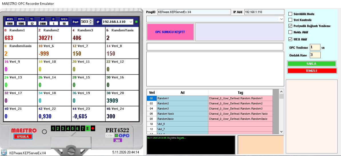
When one of the discovered OPC DA servers is selected, the tags defined on that server are displayed in a tree structure. The user can select the required tags from this tree and add them to the program's 192-point MODBUS list. This makes it possible to select only the data that needs to be transferred to the upper-level system from the potentially extensive tag space of the OPC server.
button to open the OPC configuration window on the right side of the program.OPC DA tag structure: OPC DA servers generally expose process variables through a hierarchical address space. The tree view makes it easier to navigate folders and tag groups and select the required process variable. The OPC DA standard defines real-time data access, which may include fields such as value, quality, and timestamp.
The publishing IP address and publishing port used to make MODBUS data available are selected in the upper section of the program. This address and port form the access point that SCADA, HMI, PLC, or other MODBUS TCP clients use to connect to the gateway. The default port for MODBUS TCP is 502.
Data publishing format:
Each 32-bit value is made available using two MODBUS Holding Registers. To interpret the relevant data correctly in the upper-level system, both registers must be read together, and the 32-bit data interpretation and byte/word order used by the device or driver must be compatible.
MODBUS registers are 16-bit data areas. Therefore, a single 32-bit process value is carried across two registers. MODBUS read configurations in the upper-level system must be arranged according to the gateway's data ordering and its two-register data structure.
Addressing note: Whether MODBUS client addresses are displayed using zero-based or one-based numbering depends on the software being used. Register starting addresses and the register/word order of 32-bit values should be verified on both the gateway and upper-level system during commissioning.
Options related to OPC connectivity, data display, and program behavior
can be configured in the settings panel on the left side of the program.
Changes to the settings are saved using the  (SAVE) button.
To transfer the settings to the main application, the
 (APPLY)
button on the main screen on the right must also be clicked.
| Setting | Function |
|---|---|
| Süreklilik | Automatically restarts the application if the program is closed. |
| WEB Aktif | Enables the integrated WEB Server. Published data and MODBUS addresses can be monitored live in a web table. |
| Nokta Aktif | Uses a period (.) as the decimal separator. If not selected, a comma (,) is used. |
| Periyodik Bağlantı Yenileme | Re-establishes or refreshes the connection to the OPC DA server at specified intervals. |
| OPC Yenileme Aralığı | Defines the time interval used for periodic OPC connection renewal. |
| Ondalık Hane Basamak Sayısı | Defines the number of decimal places used when displaying data. |
Saving and applying settings:
(SAVE) button to save the configuration. (APPLY) button on the main screen on the right.
Tags selected from the OPC DA server are transferred to the program's
192-point MODBUS list. The  (RESET) button is used when
the existing list needs to be cleared completely. This operation resets
the 192-point list; the OPC tags must be selected again to transfer data.
Caution: The TEMİZLE button resets the existing 192-point configuration list. Before using it, make sure that any tag selections and configuration settings that need to be retained have been saved. After changing the list or settings, click the UYGULA button on the main screen on the right.
When the  (Web Active) option in the settings panel is
selected, the integrated WEB Server can be started. This allows the
data published by the gateway through MODBUS TCP, together with its
MODBUS addresses, to be displayed live in a table using a web browser.
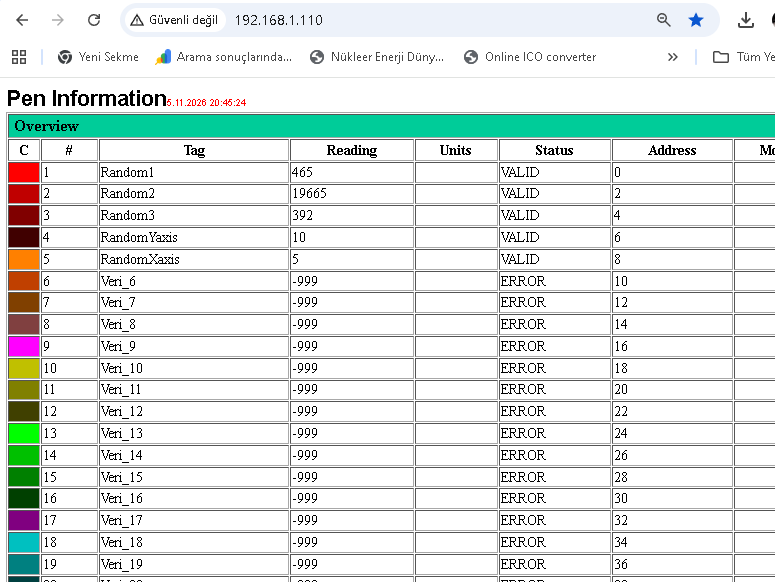
The WEB table helps users check the values read from OPC DA tags and their corresponding MODBUS addresses during commissioning and operation. This screen is intended for monitoring and verification; it is not a separate data transfer protocol that replaces the MODBUS TCP connection.
When the Süreklilik option is enabled, the program is configured to restart itself automatically if it is closed. This option can be used in installations where the gateway application is expected to run continuously on the operating computer.
The Periyodik Bağlantı Yenileme option periodically renews the connection to the OPC DA server at specified intervals. The renewal interval is defined in the OPC Yenileme Aralığı field in the settings panel. This feature can be used in scenarios where the OPC connection is intended to be re-established periodically during long-term operation.
Operational note: Automatic program restart and periodic OPC connection renewal do not, by themselves, prevent situations such as computer shutdown, power failure, network faults, or the OPC server becoming unavailable. In applications requiring continuous operation, the computer, network, OPC DA server, and DCOM configuration must be evaluated together.
OPC DA is part of the OPC Classic family and uses Microsoft COM/DCOM technology. If the OPC DA server and the gateway run on the same computer, the connection can be established through local COM. If they run on different computers, Windows network access, DCOM permissions, user accounts, and firewall rules must be configured correctly.
The OPCEnum service can be used to discover OPC servers on remote computers. Therefore, when troubleshooting server discovery and connection issues, the status of the OPCEnum service on the target computer, the OPC Server ID/ProgID information, and DCOM access permissions should be checked.
Important: Remote OPC DA connections may require TCP 135 and dynamically assigned RPC ports for DCOM/RPC communication. Firewall and network rules should be configured in accordance with the organization's information security policies, allowing access only to the required clients and servers. DCOM settings may vary depending on the operating system and OPC server manufacturer.
Making OPC DA data available through MODBUS TCP allows process information from an existing OPC infrastructure to be transferred to different systems operating as MODBUS TCP clients. This gateway approach can be particularly useful in architectures where the OPC DA server is accessible, but the upper-level system communicates through MODBUS TCP.
| Application | Potential Use |
|---|---|
| Integration of legacy SCADA systems | Transferring process values from an OPC DA server to legacy SCADA/HMI systems that support only MODBUS TCP clients. |
| Data exchange between PLCs and control systems | Making selected variables available through OPC DA readable by PLCs or control systems equipped with a MODBUS TCP client. |
| Energy monitoring and management | Retrieving power, energy, and status information available in OPC DA tags through MODBUS TCP for energy management software or analyzer systems. |
| Production and process monitoring | Transferring temperature, pressure, flow, level, and production values exposed through OPC DA by DCS, PLC, or process control software to another system. |
| HVAC and building automation | Making boiler, chiller, air handling unit, and building control data collected by an OPC DA server available to MODBUS TCP-based monitoring systems. |
| Remote monitoring and data acquisition | Transferring selected process values from an OPC DA infrastructure to remote monitoring or data acquisition applications supporting MODBUS TCP. |
| Preserving existing automation investments | Making existing data accessible through an OPC DA server available to new systems requiring a MODBUS TCP interface, without re-sourcing the original data. |
| Testing, commissioning, and system integration | Enabling the transfer of OPC DA tags to the MODBUS TCP register area to verify upper-level system connectivity and data mapping. |
Architecture note: MAESTROrecsimOPC publishes selected tag values from the OPC DA server in the MODBUS TCP Holding Register area. Therefore, access to the OPC DA server and access by the MODBUS TCP client to the gateway are two separate communication paths. Network access, security rules, data update behavior, and register mapping must be verified independently on both sides.
button in the lower-left corner to open the OPC configuration window. (SAVE) button and click (APPLY) on the main screen on the right. (WEB Active),  (Auto-Restart Mode), and
 (Periodic Connection Renewal) options as required.
MAESTROrecsim OPC DA has been developed to read selected process data from OPC DA servers and transfer it to upper-level systems through a single MODBUS TCP server. By publishing OPC DA tag values in the MODBUS TCP Holding Register area, it enables SCADA, HMI, PLC, and data acquisition systems to access this data through MODBUS TCP.
Operating requirements: Access to the OPC DA server must be available for the program to operate correctly. For connections to OPC DA servers on remote computers, the necessary network access, DCOM permissions, and firewall rules must be configured. The IP address and port number used for MODBUS TCP publishing can be configured within the program. The default publishing port is 502.
Related files:
Free Software Download Center
Software for industrial data collection, monitoring, and analysis.

Technical Support
Software documentation, sample code, and practical technical information.
You can contact us regarding EOS software, technical documentation, or industrial data communication.