
Free Software Download Center
Software for industrial data collection, monitoring and analysis.
MOBILE HPP MONITORING • SCADA DATA MAPPING • ALARM MANAGEMENT • REMOTE ACCESS
HYDRO MOBILE is a solution developed as an integrated component of EOS LIVE EVENTS, enabling real-time monitoring of hydroelectric power plant units through mobile devices.
With this system, users can monitor the current operating status of generating units, electrical and hydraulic parameters, and active alarms from a mobile phone or tablet, even when they are not physically present at the power plant.
This page provides a comprehensive explanation of the required procedures, from HYDRO MOBILE configuration and SCADA data and alarm mapping to alarm filter configuration, network settings and port forwarding.
Today, remote monitoring and rapid response have become important operational requirements for power generation facilities.

HYDRO MOBILE addresses this need by providing operators and technical personnel with access to power plant data independent of time and location.
The system presents data obtained from the SCADA infrastructure through a simple and easy-to-understand mobile interface. It also enables critical alarm conditions to be monitored through mobile devices.
Important: Running the mobile software alone is not sufficient for HYDRO MOBILE to operate correctly. Power plant and unit information must be defined, SCADA data and alarm mappings must be configured, the data to be displayed must be selected, and the required network and port configurations must be completed.
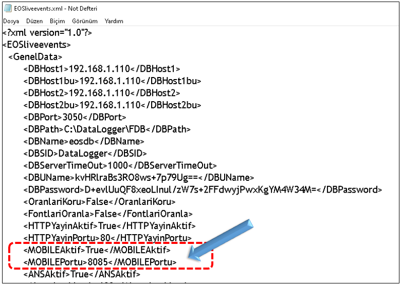
To use the HYDRO MOBILE feature, the mobile service must be enabled in the EOSliveevents.xml configuration file, and the data communication port to be used must be specified.
| Parameter | Description |
|---|---|
| MOBILEAktif | Determines whether the HYDRO MOBILE feature is enabled or disabled. When set to True, the mobile monitoring system is enabled. |
| MOBILEPortu | Specifies the port used for HYDRO MOBILE data communication. The recommended value is 8085. Another available port may be selected if required. |
WARNING: Make sure that the port selected for MOBILEPortu is not being used by another service on the network. If external access is required, the corresponding port must also be forwarded in the firewall and modem/NAT configuration.
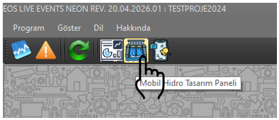
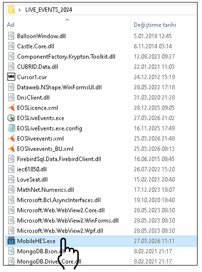
Before configuring HYDRO MOBILE, the MobileHES.exe software must first be started.
The MobileHES software can be accessed in two ways:
After MobileHES is opened, power plant information can be defined and unit-based SCADA data and alarm mapping can be performed.
The MobileHES main interface consists of 5 main panels for performing the different configuration operations of the HYDRO MOBILE system.
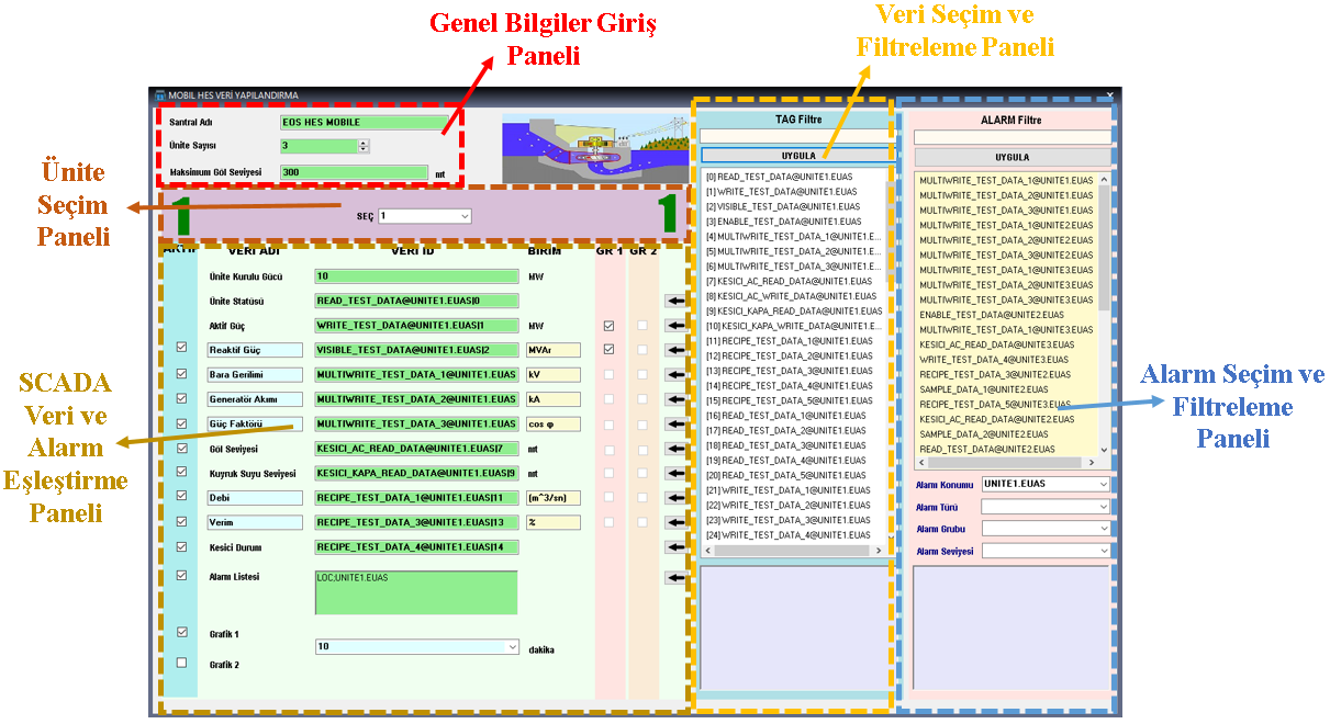
This section is used to enter basic power plant information such as the plant name, number of units and maximum reservoir elevation.
Allows the user to select the unit for which data and alarm configuration will be performed. Configuration fields associated with the selected unit become active.
This section lists real and virtual data defined in the SCADA project. The filtering feature allows the required data to be found quickly among a large number of data points.
Allows the user to determine the alarm types, locations, groups and levels to be displayed on the mobile screen.
This section is used to associate TAG and ALARM elements defined in SCADA with their corresponding parameters on the HYDRO MOBILE screen.
During the first stage of configuration, the basic information about the power plant must be defined correctly.
Entering this information correctly is important for ensuring that the unit-based data and alarm configurations performed in subsequent stages can be completed properly.
The basic operating principle of HYDRO MOBILE is based on mapping the data available in the SCADA system to meaningful parameters displayed on the mobile screen.
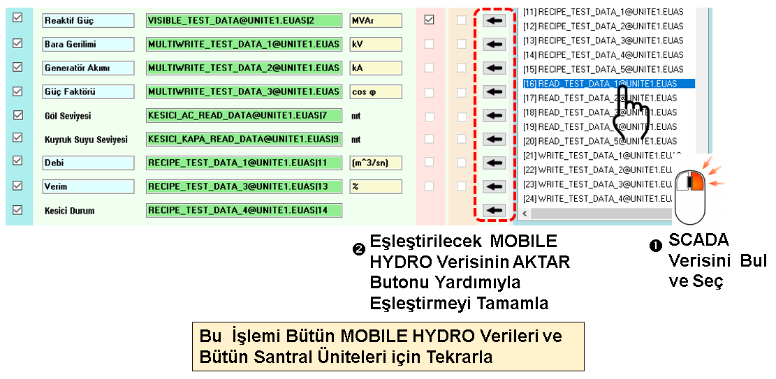
When a unit is selected from the Unit Selection Panel, the data fields associated with that unit become active.
The following parameters can be used by default:
Flexible data structure: The user can replace the default SCADA data for parameters such as Reactive Power, Bus Voltage, Generator Current, Power Factor, Flow Rate and Efficiency.
Parameter names and units can also be changed according to user requirements. This allows the HYDRO MOBILE interface to be adapted to the SCADA data structure of different facilities.
Light green field: Indicates that data mapping has been successfully completed for the field.
Light red field: Indicates that no SCADA data has yet been assigned to the field.
This color coding allows users to quickly determine which fields have been completed and which fields have not yet been configured, even in projects containing a large number of parameters.
Whether each parameter is displayed on the HYDRO MOBILE screen can be determined using the ACTIVE option.
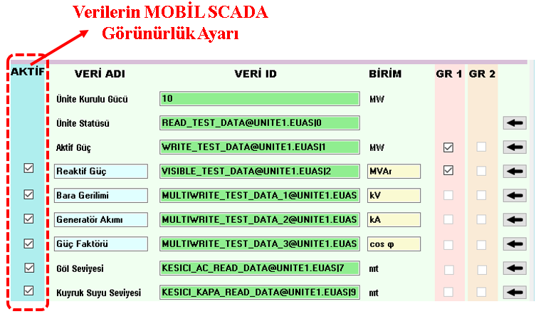
This allows unnecessary parameters to be removed from the mobile interface for different facility or unit types, resulting in a simpler and more purpose-oriented monitoring screen.
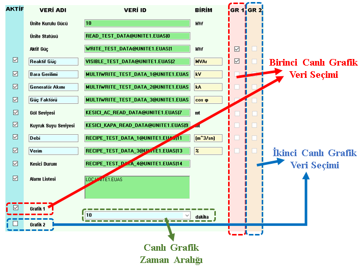
The data displayed in live graphs on HYDRO MOBILE is determined using the GR1 and GR2 selections.
A maximum of 2 data points can be assigned to each graph.
The period displayed on the time axis of the graphs is specified in minutes using the Live Graph Time Range parameter.
A large number of alarms may be defined in SCADA systems. Displaying all of these alarms on the mobile screen may result in unnecessary information overload and make monitoring more difficult.
Therefore, it is recommended that HYDRO MOBILE display only alarm types that are operationally important, critical or high-priority.
The Alarm Selection and Filtering Panel can be used to define the scope of alarms to be displayed in detail.
The user can manually select specific alarms from the alarm list. This method is suitable when selecting a small number of clearly defined alarms.
Text filtering can be performed based on the alarm name or description. This is especially useful in projects containing hundreds of alarms, allowing the required alarm to be found quickly.
Alarm locations defined in the SCADA project can be included in the filtering criteria.
For example, locations such as Unit 1, Unit 2 or Switchyard can be selected so that only alarms associated with the relevant area are displayed on the mobile screen.
Example: If the user is monitoring only Unit 1 on the mobile screen, it would be more appropriate to display only the alarms associated with Unit 1 rather than bringing the alarm activity of the other units onto the screen.
The Alarm Filter Settings screen allows alarms to be filtered according to type, group and level criteria.
The user can include a specific alarm type, group or level in the filter, or exclude unwanted alarm classes from the filtering scope.
| Expression | Meaning | Example |
|---|---|---|
| inc_ | Includes the relevant alarm type, group or level in the filter. | inc_Critical |
| exc_ | Excludes the relevant alarm type, group or level from the filter. | exc_Info |
For example, inc_Critical, inc_Mechanical and inc_Analog expressions include the corresponding classes in the filter.
Expressions such as exc_Info, exc_TestAlarms and exc_System exclude the corresponding classes from the filtering scope.
The Alarm Filter Settings screen allows multiple filtering criteria to be used simultaneously. This makes it possible to create highly specific and targeted alarm lists.
Example Scenario
As a result of this configuration, only mechanical alarms associated with Unit 1 at Critical and Warning levels are included in the HYDRO MOBILE unit screen.
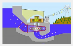
When all required data mappings for a unit have been completed successfully, the HPP animation becomes active on the MobileHES screen.
An active HPP animation visually indicates that the required data definitions for the relevant unit have been completed.
This indicator allows the user to quickly determine whether the configuration process has been completed without requiring a separate checklist.
If the animation is not active, some data fields associated with the relevant unit may not yet have been defined. In this case, the data fields displayed in light red should be checked.
If the user does not want the Alarm List to be displayed on the MOBILE SCADA screen, the ACTIVE option for the Alarm List can be cleared.
This removes the alarm list from the mobile interface, allowing only the required data fields to be displayed.
To use HYDRO MOBILE from mobile devices over an external network, the required ports must be forwarded to the computer on which the system is running.
It is important to correctly configure the following two communication ports:
LIVE EVENTS uses port 80 by default.
This port must be forwarded from the external network to the internal IP address of the computer running LIVE EVENTS.
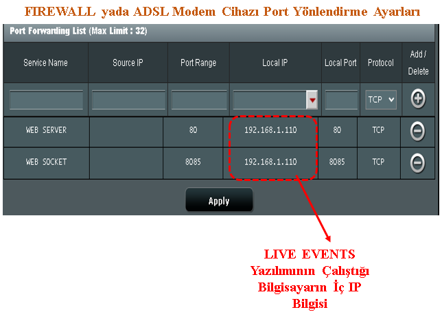
The MOBILEPortu parameter is used for HYDRO MOBILE data communication. The recommended value is 8085.
Requests arriving at port 8085 from the external network must be forwarded to the internal IP address of the computer running LIVE EVENTS.
SECURITY WARNING: When configuring port forwarding, only the ports that are required should be exposed to external access. Whenever possible, access should be restricted based on IP addresses, and firewall rules should be configured carefully.
After completing the network and port forwarding configuration, the user can open a web browser on the mobile device and access the facility's public IP address.
If HTTP is configured to use port 80, it is not necessary to specify the port number at the end of the address.
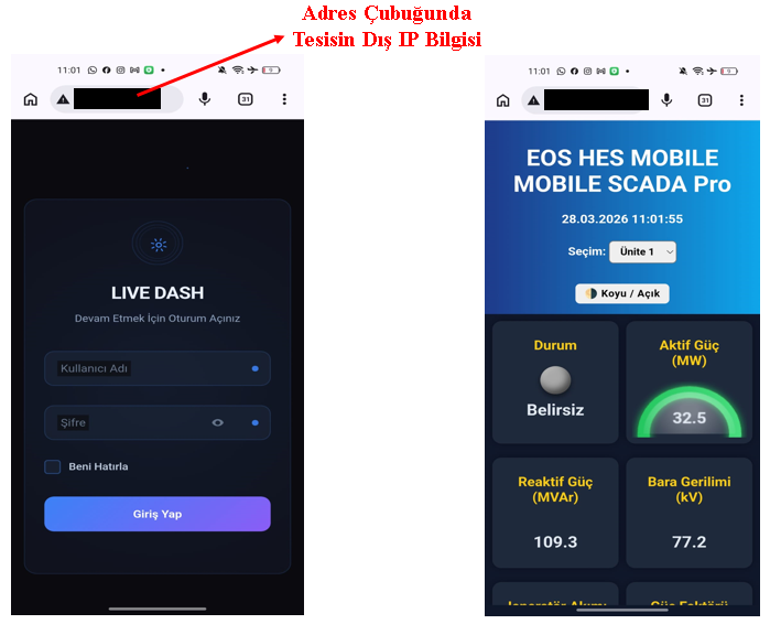
If a different port is used, the port number must be specified after the IP address using a colon.
When the address is accessed, the user is presented with the LIVE DASH authentication screen.
After logging in with an authorized username and password defined in the SCADA project, the user is connected to the HYDRO MOBILE system.
After a successful login, the data and alarms of the configured units can be viewed live through the mobile device.
Bringing HYDRO MOBILE into operation consists of several fundamental stages that complement one another.
HYDRO MOBILE is an integrated mobile monitoring solution that uses the EOS LIVE EVENTS infrastructure to enable monitoring of hydroelectric power plant data and alarms from mobile devices.
To use the system effectively, plant and unit information must be defined correctly, SCADA data must be mapped to the corresponding mobile parameters, and the data set displayed on the mobile screen must be carefully selected.
In addition, proper configuration of alarm filters is essential to ensure that users receive only the critical information they need. By combining location, alarm type, group and level filters, alarm lists can be created to meet different operational requirements.
With correct network and port configuration, authorized users can access live unit data and alarms from their mobile devices without being physically present at the power plant.
The primary purpose of HYDRO MOBILE is not merely to transfer SCADA data to a mobile device, but to provide the information required for power plant operation in a simple, selectable, filterable and real-time mobile monitoring environment.
Free Software Download Center
Software for industrial data collection, monitoring and analysis.

Technical Support
Documentation, sample code and application-oriented information for EOS software.
You can contact us regarding EOS software, technical documentation, or industrial data communication.